MLRK1-FAL17 Insert Instructions
Open the original PDF document
View PDF


mlrk1-FAL17
INSERT INSTRUCTIONS
The Command Access MLRK1-FAL17 is a field installable motorized latch-retraction kit for:
- MRLK1-FAL17 Falcon 16 & 17 series devices
- MRLK1-FC37 First Choice 36 & 37 series devices
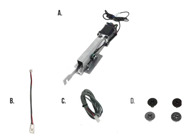
- 1- Motor Mount w/MM5 A.
- 1- 50944 Molex Pigtail B.
- 1- 50030- 6' Lead w/ VD Connector C.
-
2- 40124 10-24 x 3/8" Phillips Screws (Silver)
D.
- 2- 40125 10-24 x 3/8" Phillips Screws (Black)
SPECIFICATIONS
- Input Voltage: 24VDC +/- 10%
- AVERAGE LATCH RETRACTION CURRENT: 900 mA
- Average holding current: 215 ma
- Wire gauge: Minimum 18 gauge
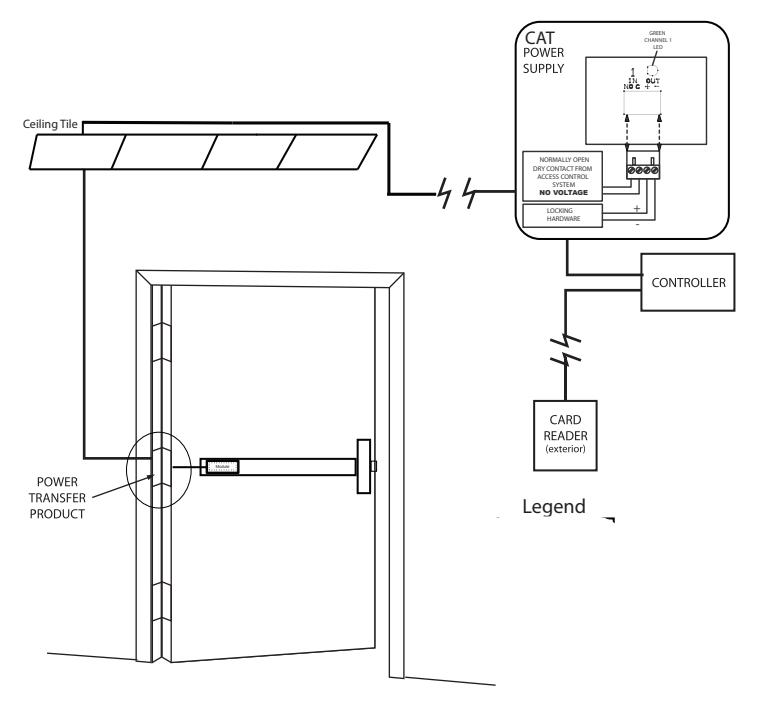
- Direct wire run no relays or access control units in-between power supply & module
Recommended Power Supplies:
All Command Access exit devices & field installable kits have been thoroughly cycle tested with Command Access power supplies at our factory. If you plan on using a non-Command power supply it must be a filtered & regulated linear power supply.
Kit Includes Tools Required
Cordless Drill or Phillips Screwdriver Hacksaw
Optional built-in rex
- SPDT Rated .5a @24V
- green= Common (C)
- Blue = normally open (NO)
- grey = normally closed (NC)
TECHNICAL INFORMATION

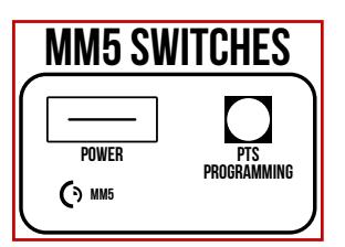
SETTING PUSH TO SET (PTS)
→ **IMPORTANT INFO** ←
MAKE SURE TO SET PTS BEFORE FINISHING INSTALLATION
- STEP 1 - To enter PTS mode: Depress MM5 button & apply power. The device will emit 1 SHORT beep. The device is now in PTS mode.
- STEP 2 - While depressing the push pad, apply power. (i.e. presenting the credential to the reader).
- STEP 3 Continue to keep pad depressed, the device will emit 1 LONG Beep. After the beep has stopped, release the pad and now the adjustment is complete. test the new location, If not to your liking repeat the 3 steps.
TROUBLESHOOTING & DIAGNOSTICS
| BEEPS | EXPLANATION | SOLUTION |
|---|---|---|
| 2 Beeps | Over Voltage | > 30V unit will shut down. Check voltage & adjust to 24 V. |
| 3 Beeps | Under Voltage | < 20V unit will shut down. Check voltage & adjust to 24 V. |
| 4 Beeps | Failed Sensor | Verify all 3 sensor wires are installed correctly. Replace sensor if problem persists by contacting office. |
| 5 Beeps | Retraction or dogging failure | After 1st fail: 5 beeps then immediately attempts to retract again. After 2nd fail: 5 beeps with pause in-between for 30 seconds then device attempts to retract again. After 3rd fail: 5 beeps every 7 minutes, device will not attempt to retract. To Reset: Depress bar for 5 seconds at any time. |
I n s ta l l at i o n I n s t r u c t i o n s

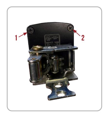
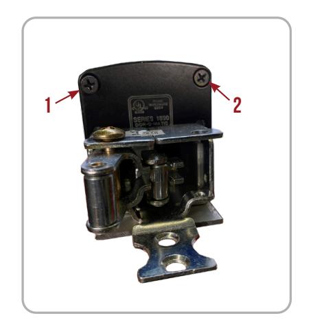
- Remove Screws securing the Push Pad End Caps and slide off Push Pad . 1.
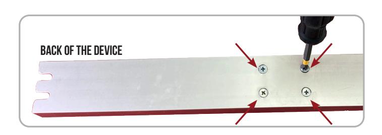
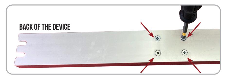
- Remove 4 Screws from back of the Baserail . 2.
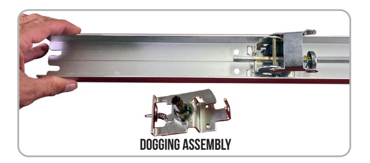
Remove Dogging Assembly and discard. 3.
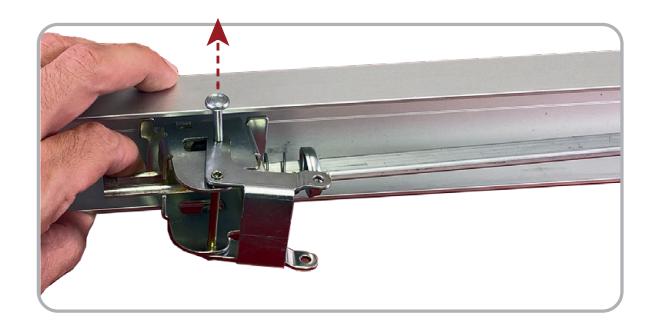
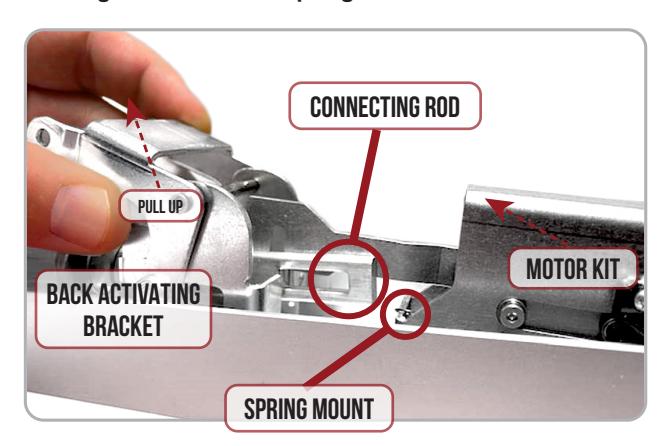
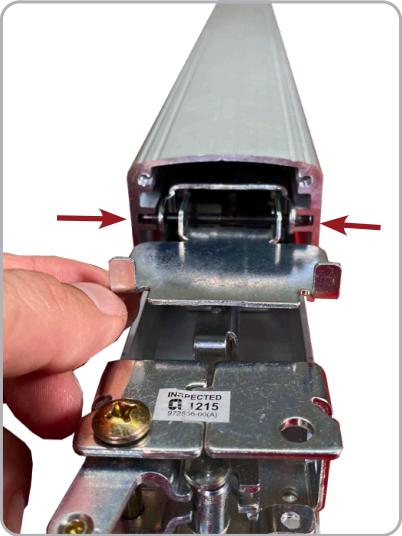
Lift up Back Activating Bracket and remove Roll Pin to release. 4.
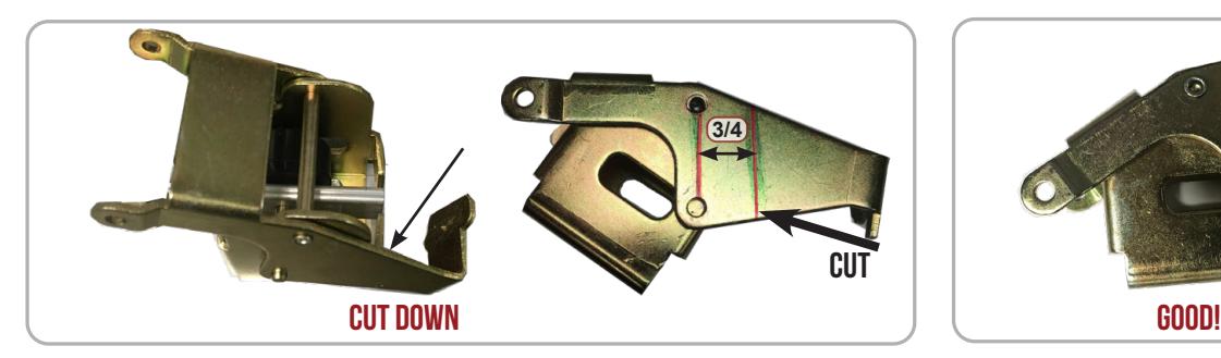
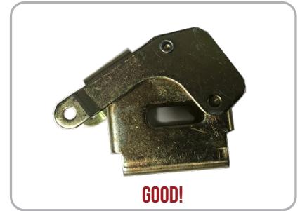
* First Choice Devices Only : Cut down Back Activating Bracket to remove Dogging Extension . 5.
Remove Activating Bracket then remove Rubber Bumper . 6.
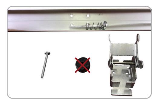

Reassemble Activating Bracket . Re-install into Baserail by inserting Bottom Pin through Connecting Rod . 7.
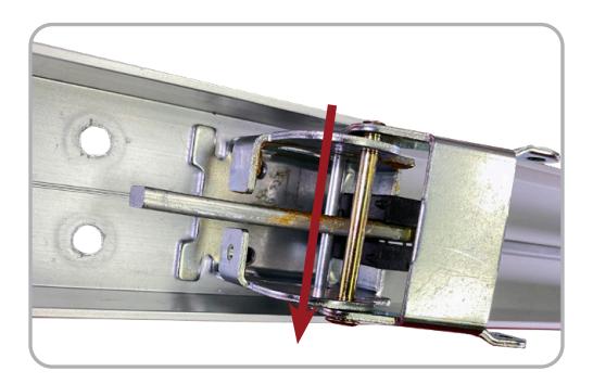
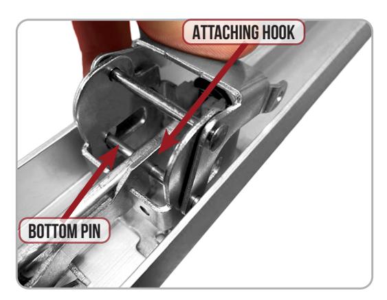
Drop the Motor Kit 's attatching hook on to the Bottom Pin . Make sure to keep the hooks at an angle so that the Connecting Rod avoids the Spring Mount . 8.
Line up the Back Activating Bracket and Motor Mount screw holes with the existing screw holes on the Exit Device . 9.
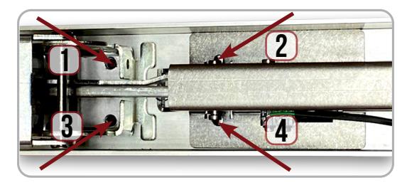
Secure the Motor Kit and Back Activating Bracket from the back of the device with (4) of the Finished Screws . 10.

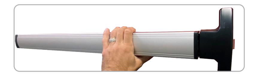
11. Re-install Top Pins on both Activating Brackets and slide on the Push Pad making sure Pins are in the proper channel.
12. Re-install Screws securing the Push Pad End Caps on the front & back.
13. Set the "Push to Set Adjustment" following the steps below, remembering to turn the Programming Switch to the off position when completed.
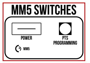
SETTING PUSH TO SET (PTS)
→ **IMPORTANT INFO** ←
MAKE SURE TO SET PTS BEFORE FINISHING INSTALLATION
- STEP 1 - To enter PTS mode: Depress MM5 button & apply power. The device will emit 1 SHORT beep. The device is now in PTS mode.
- STEP 2 - While depressing the push pad, apply power. (i.e. presenting the credential to the reader).
- STEP 3 Continue to keep pad depressed, the device will emit 1 LONG Beep. After the beep has stopped, release the pad and now the adjustment is complete. test the new location, If not to your liking repeat the 3 steps.