MLRK1-FAL17 2 Insert Instructions
Open the original PDF document
View PDF


mlrk1-FAL17
INSERT INSTRUCTIONS
The Command Access MLRK1-FAL17 is a field installable motorized latch-retraction kit for:
- MRLK1-FAL17 Falcon 16 & 17 series devices
- MRLK1-FC37 First Choice 36 & 37 series devices
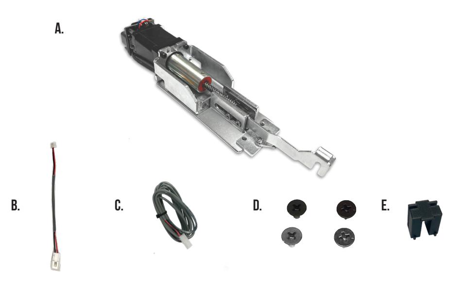
Kit Includes Tools Required
- 1- Motor Mount w/MM4S A.
- 1- 50944 Molex Pigtail B.
- 1- 50030- 6' Lead w/ VD Connector C.
-
2- 40124 10-24 x 3/8" Phillips Screws (Silver)
D.
- 2- 40125 10-24 x 3/8" Phillips Screws (Black)
- 1- 51211 Plastic Spacer Guide E.
Cordless Drill or Phillips Screwdriver Hacksaw
SPECIFICATIONS
- Input Voltage: 24VDC +/- 10%
- Wire gauge: Minimum 18 gauge
- Direct wire run no relays or access control units in-between power supply & module
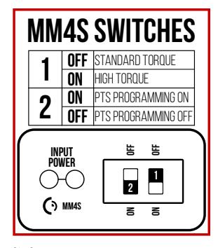
Standard Torque Mode
Average Latch Retraction Current: 900mA Average Holding Current: 215 mA
High Torque Mode
Average Latch Retraction Current: 2 Amp Average Holding Current: 250 mA
Recommended Power Supplies:
All Command Access exit devices & field installable kits have been thoroughly cycle tested with Command Access power supplies at our factory. If you plan on using a non-Command power supply it must be a filtered & regulated linear power supply.
TECHNICAL INFORMATION

SETTING PUSH TO SET (PTS)

MAKE SURE TO SET PTS BEFORE FINISHING INSTALLATION
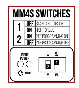
- STEP 1 - Select your preferred torque mode (ships in standard torque). Press the device push pad to the desired setting. (We recommend to fully depress and release 5%, giving the device room for changing door conditions.)
- STEP 2 - While depressing the push pad, apply power.
- STEP 3 Continue to keep the pad depressed, the device will beep 6 times. After the beeps have stopped, release the pad and the adjustment is now set. Test the adjustment 4 to 5 times and if not to your liking repeat the above steps.
*Once you found your preferred adjustment, we recommend turning off the PTS programming switch.
TROUBLESHOOTING & DIAGNOSTICS
| BEEPS | EXPLANATION | SOLUTION |
|---|---|---|
| 2 Beeps | Over Voltage | > 30V unit will shut down. Check voltage & adjust to 24 V. |
| 3 Beeps | Under Voltage | < 20V unit will shut down. Check voltage & adjust to 24 V. |
| 4 Beeps | Failed Sensor | Verify all 3 sensor wires are installed correctly. Replace sensor if problem persists by contacting office. |
| 5 Beeps | Retraction or dogging failure | After 1st fail: 5 beeps then immediately attempts to retract again. After 2nd fail: 5 beeps with pause in-between for 30 seconds then device attempts to retract again. After 3rd fail: 5 beeps every 7 minutes, device will not attempt to retract. To Reset: Depress bar for 5 seconds at any time. |
| 6 Beeps | PUSH TO SET | Device is recording it's new position and power mode after the 6th beep. |
I n s ta l l at i o n I n s t r u c t i o n s

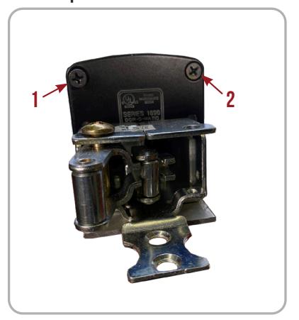
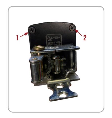
Remove (2) Screws securing the Push Pad End Caps on the front & back, and then the Push Pad End Caps .Place all to the side. 1.
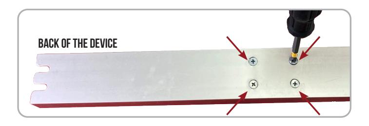
Remove 4 Screws from back of the Baserail . 2.
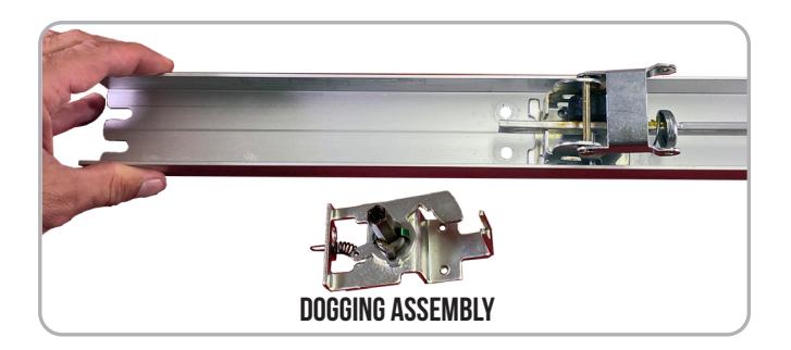
Remove Dogging Assembly and discard. 3.
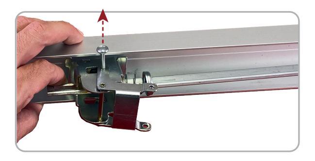
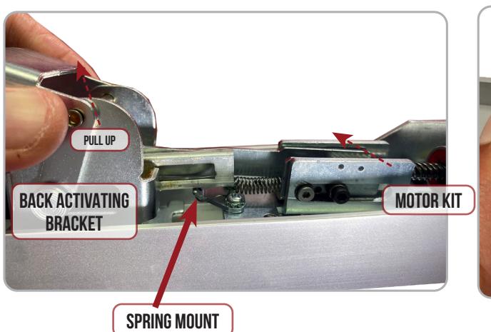
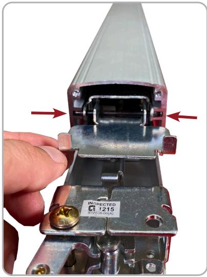
Lift up Back Activating Bracket and remove Roll Pin to release. 4.
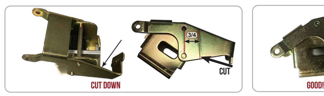
* First Choice Devices Only : Cut down Back Activating Bracket to remove Dogging Extension . 5.
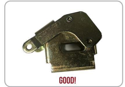
Remove Activating Bracket then remove Rubber Bumper , & Factory Spacer . 6.
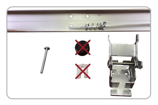

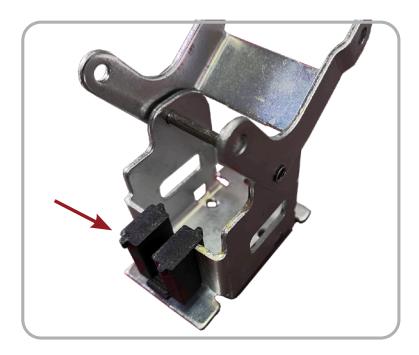
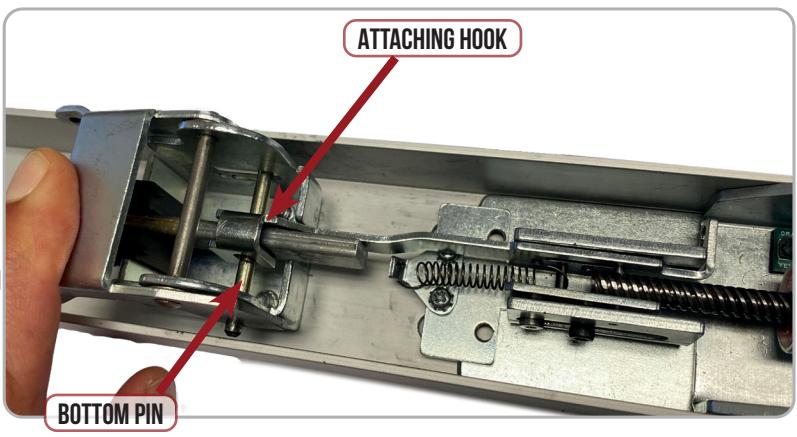
Add Replacement Spacer & reassemble Activating Bracket . Re-install into Baserail by inserting Bottom Pin through Connecting Rod . 7.
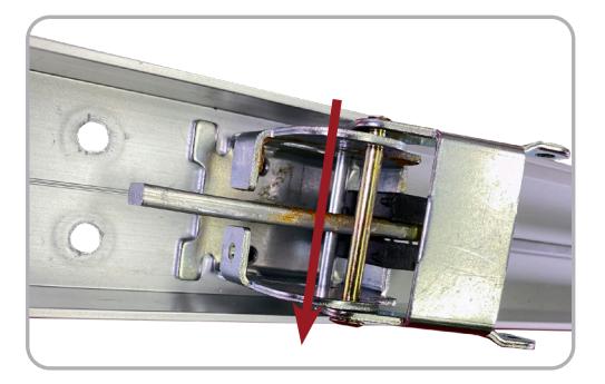
Drop the Motor Kit 's attatching hook on to the Bottom Pin . Make sure to keep the hooks at an angle so that the Connecting Rods avoids the Spring Mount . 8.
Line up the Back Activating Bracket and Motor Mount screw holes with the existing screw holes on the Exit Device . 9.
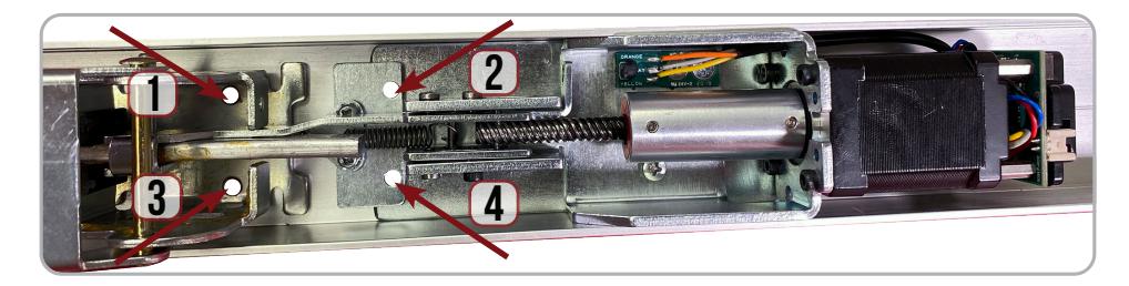
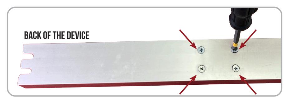
Secure the Motor Kit and Back Activating Bracket from the back of the device with (4) of the Finished Screws . 10.

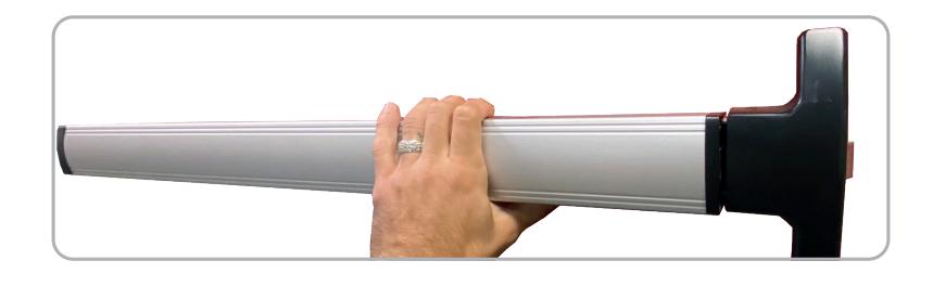
11. Re-install Top Pins on both Activating Brackets and slide on the Push Pad making sure Pins are in the proper channel.
12. Re-install (2) Screws securing the Push Pad End Caps on the front & back.
13. Set the "Push to Set Adjustment" following the steps below, remembering to turn the Programming Switch to the off position when completed.
SETTING PUSH TO SET (PTS)
→ **IMPORTANT INFO** ←
MAKE SURE TO SET PTS BEFORE FINISHING INSTALLATION
- STEP 1 - Select your preferred torque mode (ships in standard torque). Press the device push pad to the desired setting. (We recommend to fully depress and release 5%, giving the device room for changing door conditions.)
- STEP 2 While depressing the push pad, apply power.
- STEP 3 Continue to keep the pad depressed, the device will beep 6 times. After the beeps have stopped, release the pad and the adjustment is now set. Test the adjustment 4 to 5 times and if not to your liking repeat the above steps.
*Once you found your preferred adjustment, we recommend turning off the PTS programming switch.