MLRK1-DOR Insert Instructions Template
Open the original PDF document
View PDF


MLRK1-DOR
INSERT INSTRUCTIONS
The Command Access MLRK1 is a Field-installable motorized latch-retraction kit: MLRK1-DOR - Dorma 9000 series devices
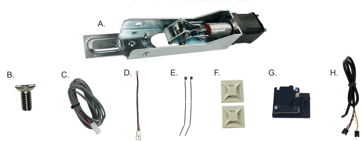
KIT INCLUDES
- A. 1 MOTOR KIT
- B. 1-40801 PHILLIPS HEAD SCREW
- C. 1- 50030 6' POWER LEAD
- D. 1- 50944 MOLEX PIGTAIL
- E. 2 40060 CABLE TIE
- F. 2 40059 MOUNTING PAD
- G. 1-60368/51186 REMOTE MM4S MODULE
- H. 1 50741 REMOTE MODULE CABLE

INSTALLATION VIDEO
OPTIONAL BUILT-IN REX
SPDT - RATED 5A @24V
BLUE = NORMALLY OPEN (NO)
GREY = NORMALLY CLOSED (NC)
GREEN= COMMON (C)
SPECIFICATIONS
- INPUT VOLTAGE: 24VDC +/- 10%
- AVERAGE LOW TOROUE LATCH RETRACTION CURRENT: 900 MA
- AVERAGE HIGH TORQUE LATCH RETRACTION CURRENT: 2A
- AVERAGE HOLDING CURRENT: 215 MA
- WIRE GAUGE: MINIMUM 18 GAUGE
- DIRECT WIRE RUN NO RELAYS OR ACCESS CONTROL UNITS IN-BETWEEN POWER SUPPLY & MODULE
RECOMMENDED POWER SUPPLIES: USE A POWER LIMITED CLASS 2 POWER SUPPLY
ALL COMMAND ACCESS EXIT DEVICES & FIELD INSTALLABLE KITS HAVE BEEN THOROUGHLY CYCLE TESTED WITH COMMAND ACCESS POWER SUPPLIES AT OUR FACTORY. IF YOU PLAN ON USING A NON-COMMAND POWER SUPPLY IT MUST BE A FILTERED & REGULATED LINEAR POWER SUPPLY.
TECHNICAL INFORMATION

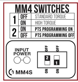
- STEP 1- SELECT YOUR PREFERRED TORQUE MODE (SHIPS IN STANDARD TORQUE) PRESS THE DEVICE PUSH PAD TO THE DESIRED SETTING. (RECOMMEND TO FULLY DEPRESS AND RELEASE 5%, GIVING THE DEVICE ROOM FOR CHANGING DOOR CONDITIONS.)
- STEP 2- WHILE DEPRESSING THE PUSH PAD. APPLY POWER. (I.E. PRESENTING THE CREDENTIAL TO THE READER).
- STEP 3- CONTINUE TO KEEP PAD DEPRESSED, THE DEVICE WILL BEEP 6 TIMES. AFTER THE BEEPS HAVE STOPPED, RELEASE THE PAD AND NOW THE ADJUSTMENT IS COMPLETE. IF NOT TO YOUR LIKING REPEAT THE 3 STEPS.
- STEP 4- ONCE YOU FOUND THE CORRECT LOCATION, TURN PTS SWITCH TO OFF POSITION.
TROUBLESHOOTING & DIAGNOSTICS
| BEEPS | EXPLANATION | SOLUTION |
|---|---|---|
| 2 BEEPS | OVER VOLTAGE | > 30V UNIT WILL SHUT DOWN. CHECK VOLTAGE & ADJUST TO 24 V. |
| 3 BEEPS | UNDER VOLTAGE | < 20V UNIT WILL SHUT DOWN. CHECK VOLTAGE & ADJUST TO 24 V. |
| 4 BEEPS | FAILED SENSOR | VERIFY ALL 3 SENSOR WIRES ARE INSTALLED CORRECTLY. REPLACE SENSOR IF PROBLEM PERSISTS BY CONTACTING OFFICE. |
| 5 BEEPS | RETRACTION OR DOGGING FAILURE | AFTER 1ST FAIL: 5 BEEPS THEN IMMEDIATELY ATTEMPTS TO RETRACT AGAIN. |
| AFTER 2ND FAIL : 5 BEEPS WITH PAUSE IN-BETWEEN FOR 30 SECONDS THEN DEVICE ATTEMPTS TO RETRACT AGAIN. | ||
| AFTER 3RD FAIL: 5 BEEPS EVERY 7 MINUTES, DEVICE WILL NOT ATTEMPT TO RETRACT. | ||
| TO RESET: DEPRESS BAR FOR 5 SECONDS AT ANY TIME. | ||
| 6 BEEPS | PUSH TO SET | DEVICE IS RECORDING IT'S NEW POSITION AND POWER MODE AFTER THE 6TH BEEP. |
I n s ta l l at i o n I n s t r u c t i o n s

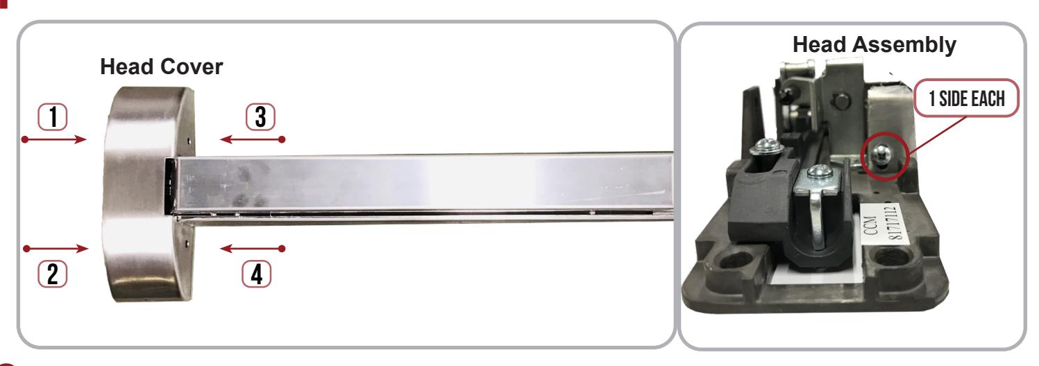
1 Remove Head Cover (4 screws) and Head Assembly (2 screws).
2 Flip the bar over and remove the 6 Screws holding the Push Pad Assembly to the Base Rail.
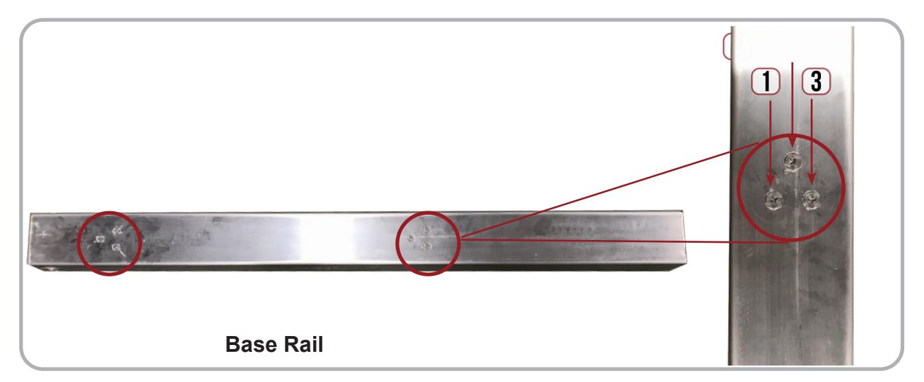
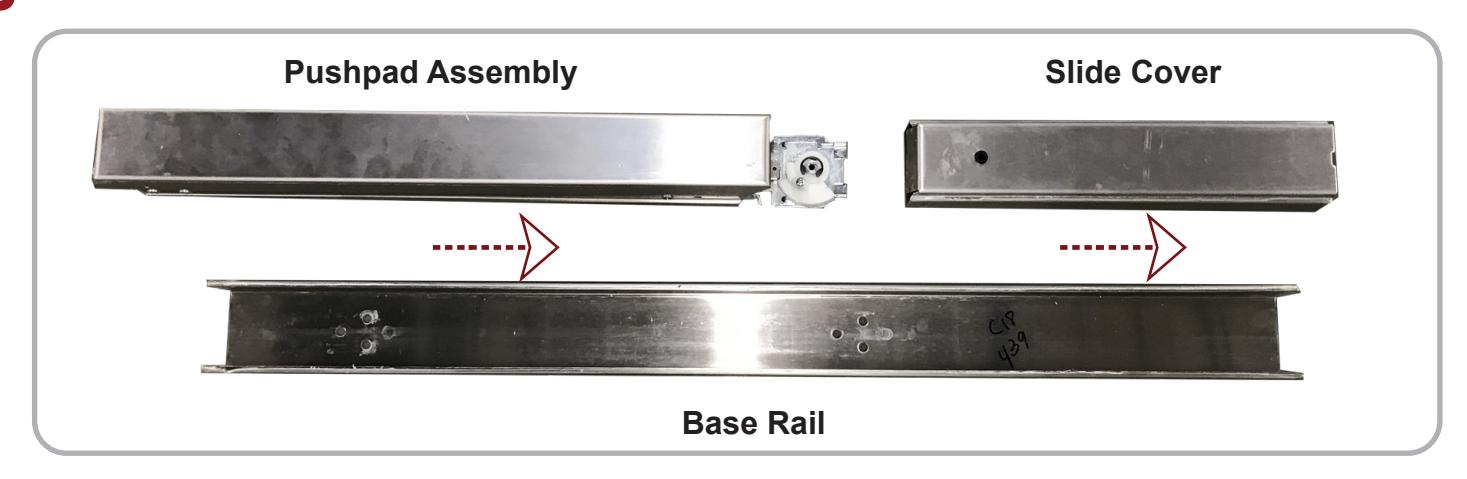
3 Slide Pushpad Assembly and Slide Cover out of the Base Rail.
I n s ta l l at i o n I n s t r u c t i o n s

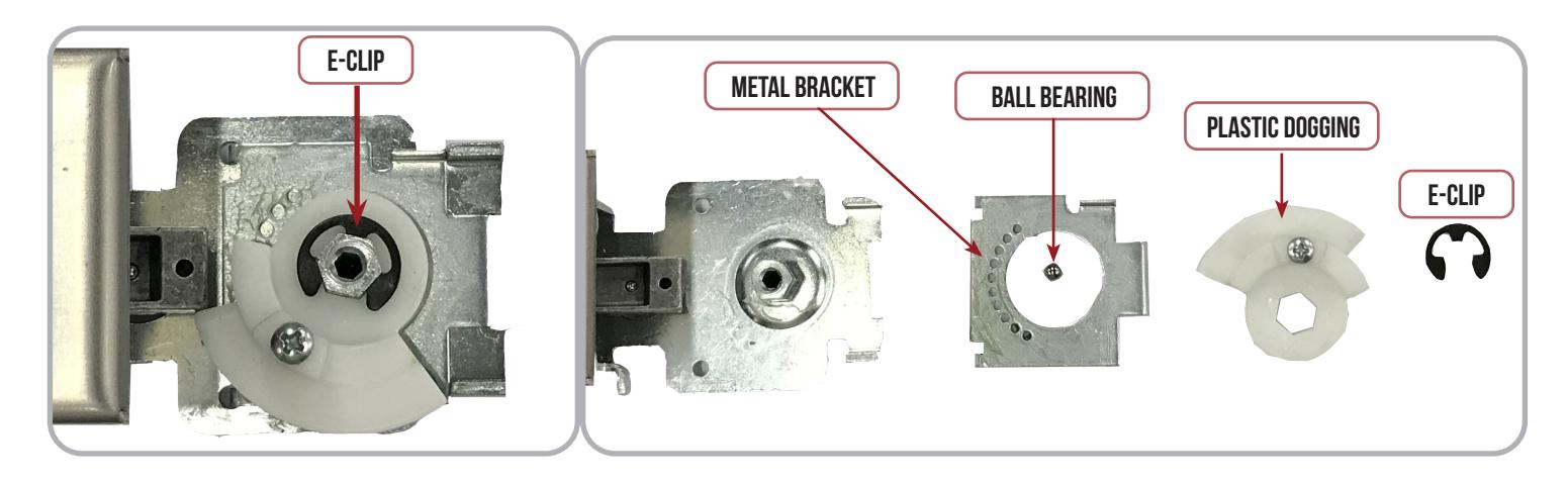
4 If you would prefer not to have Dogging on your device, simply remove the E-Clip and the Plastic Dogging Piece , Ball Bearing and Metal Bracket can be taken off.
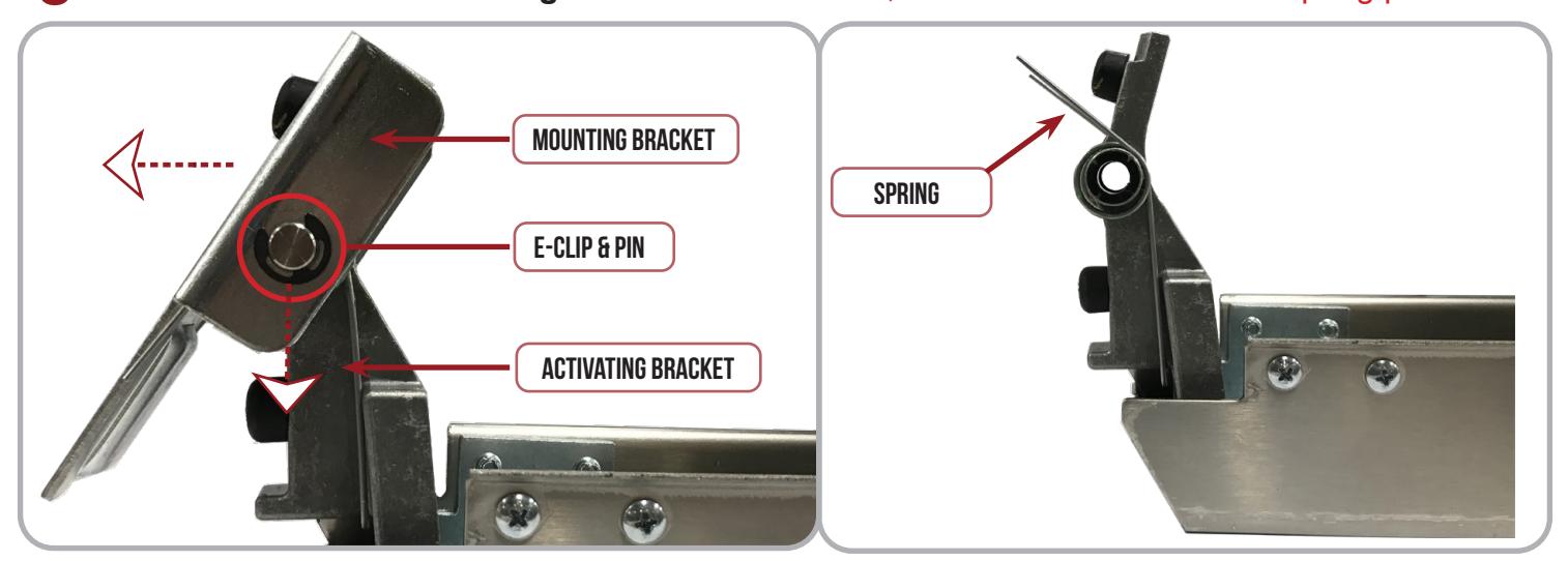
5 Flip Pushpad Assembly over and locate the Front Activating Bracket .
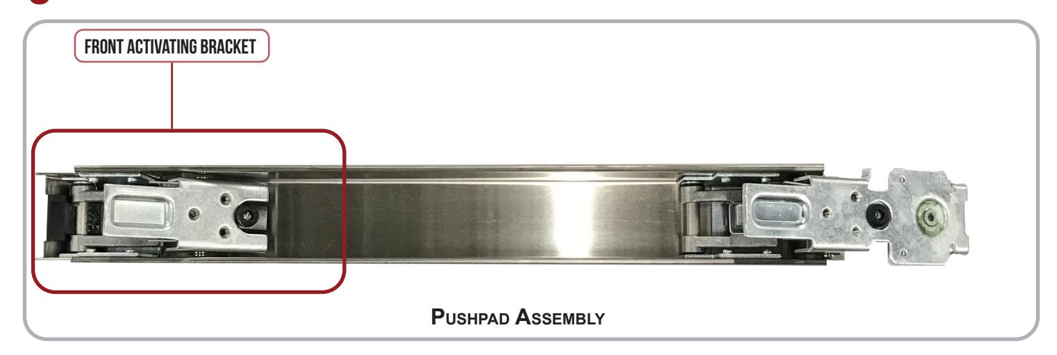
6 Remove the E-Clip from the Pin that holds the Mounting Bracket to the Activating Bracket . Slide the Pin out and take the Mounting Bracket off . * Careful , these Brackets are under spring pressure.
I n s ta l l at i o n I n s t r u c t i o n s

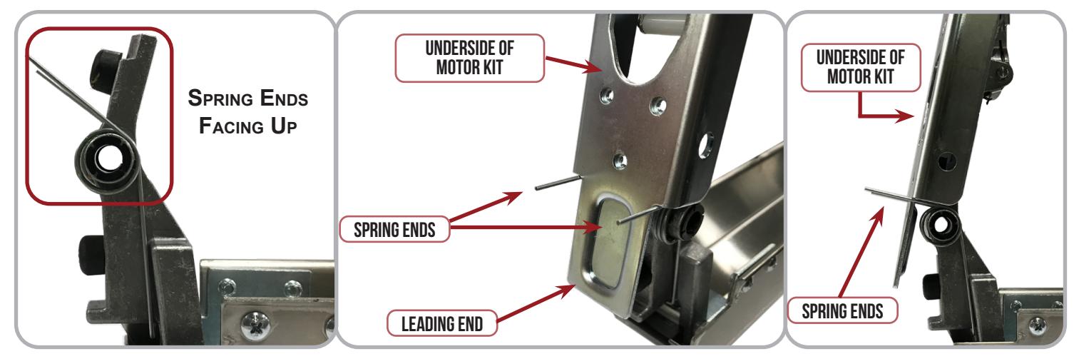
7 With the Spring Ends facing up, slide the Motor Kit down and in between them. Ensure the Spring Ends are on the sides of the Leading End of the Motor Kit Mounting Bracket .
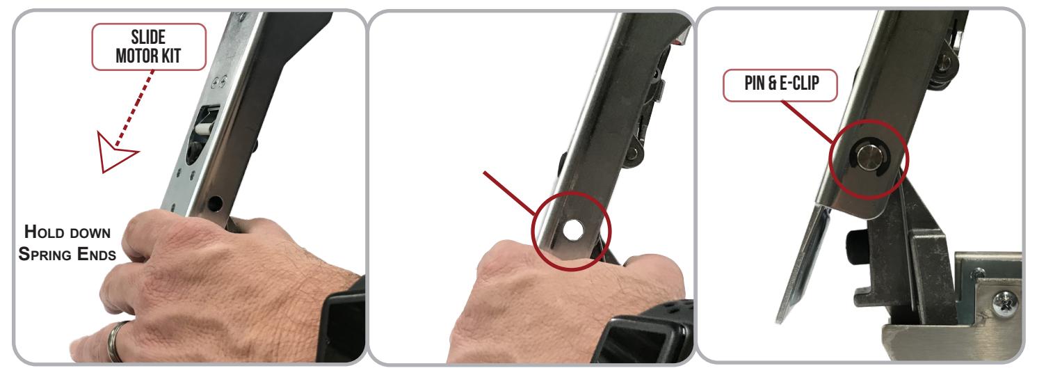
8 Use your fingers to hold down the Spring Ends and slide the Motor Kit until its cutout aligns with the Activating Bracket's Pin Hole . Re-install the Pin and secure it with the E-Clip .
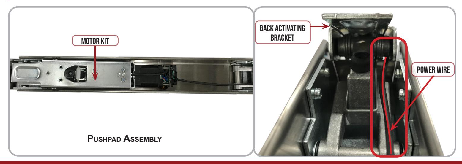
9 Lay the Motor Kit down into the Pushpad Assembly , then route the Power Wire through the Back Activating Bracket as shown.
INSTALLATION INSTRUCTIONS

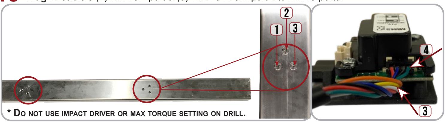
Slide the Base Rail over the Pushpad Assembly until all 6 holes are aligned, re-install the screws. Plug-in cable's (4) Pin TOP port & (3) Pin BOTTOM port into MM4S ports.
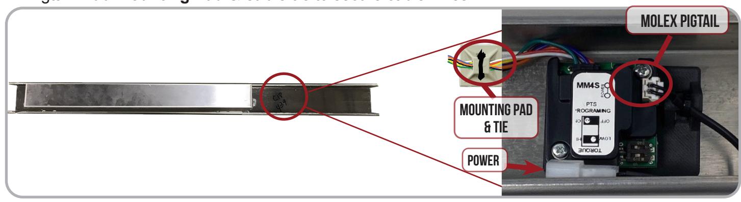
Slide the Base Rail over the Pushpad Assembly until all 6 holes are aligned, re-install the screws. Using double sided tape, secure MM4S to inside of the back of exit device housing. Connect Molex Pigtail. Add Mounting Pad & cable tie to secure cable wires.
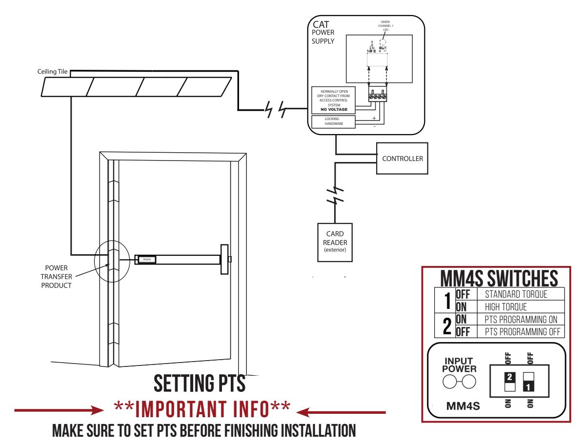
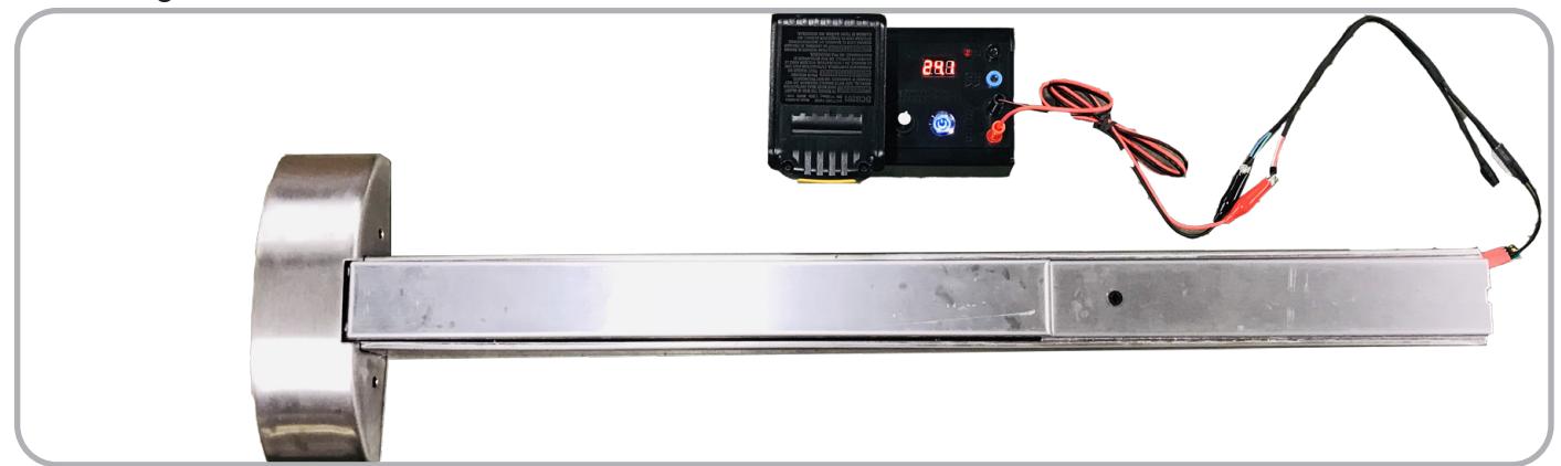
Re-install the Head Assembly, Head Cover and Cover Plate . *You may have to turn the plastic dogging piece in order to fully install the Slide Cover. Connect to Power & Set Push To Set position following the instructions below.
- STEP 1- SELECT YOUR PREFERRED TORQUE MODE (SHIPS IN STANDARD TORQUE) PRESS THE DEVICE PUSH PAD TO THE DESIRED SETTING. (RECOMMEND TO FULLY DEPRESS AND RELEASE 5%, GIVING THE DEVICE ROOM FOR CHANGING DOOR CONDITIONS.)
- STEP 2- WHILE DEPRESSING THE PUSH PAD, APPLY POWER. (I.E. PRESENTING THE CREDENTIAL TO THE READER).
- STEP 3- CONTINUE TO KEEP PAD DEPRESSED, THE DEVICE WILL BEEP 6 TIMES. AFTER THE BEEPS HAVE STOPPED, RELEASE THE PAD AND NOW THE ADJUSTMENT IS COMPLETE. IF NOT TO YOUR LIKING REPEAT THE 3 STEPS.
- STEP 4- ONCE YOU FOUND THE CORRECT LOCATION, TURN PTS SWITCH TO OFF POSITION.