MLRK1-CORInsert-Instructions-1
Open the original PDF document
View PDF


MLRK1-COR

I N S E R T I n s t r u c t i o n s
The Command Access MLRK1 is a field-installable motorized latch-retraction kit for: • MLRK1-COR - Corbin 4000/5000 and Yale 7000 series devices
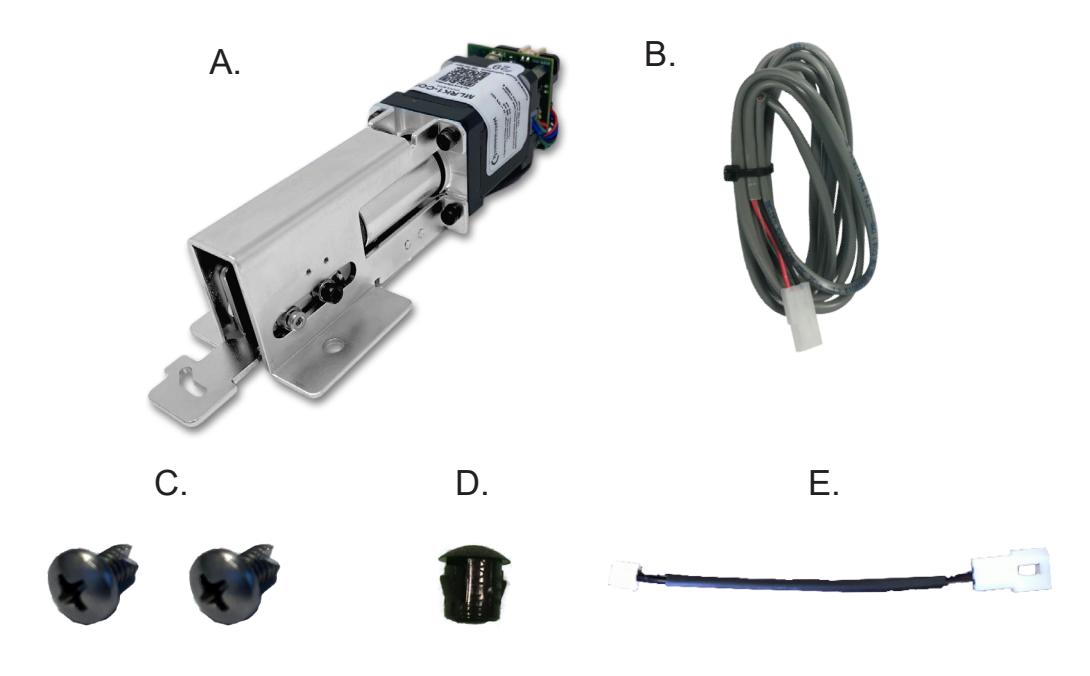
- A. 60417 MLRK1 motor
- E. 50944 MM4t Socket Lead cordless drill
- B. 50030 8' Power Lead
- C. 40176 Phillips Head Screws (x2)
- D. 40144 Dogging Hole Cap
Kit Includes Tools Required
- #2 phillips screwdriver
SPECIFICATIONS
- Input Voltage: 24VDC +/- 10% • Wire gauge: Minimum 18 gauge
- Direct wire run no relays or access control units in-between power supply & module
Standard Torque Mode
Average Latch Retraction Current: 900 mA Average Holding Current: 215 mA
High Torque Mode
Average Latch Retraction Current: 2 Amp Average Holding Current: 250 mA
Recommended Power Supplies:
All Command Access exit devices & field installable kits have been thoroughly cycle tested with Command Access power supplies at our factory. If you plan on using a non-Command power supply it must be a filtered & regulated linear power supply.
PUSH TO SET (PTS)

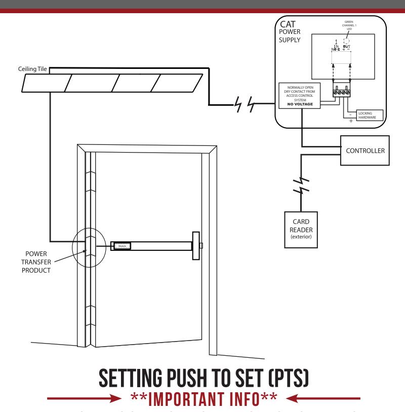
MAKE SURE TO SET PTS BEFORE FINISHING INSTALLATION
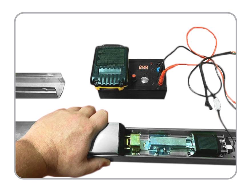
- STEP 1 - Select your preferred torque mode (ships in standard torque). Press the device push pad to the desired setting. (We recommend to fully depress and release 5%, giving the device room for changing door conditions.)
- STFP ? - While depressing the push pad, apply power.
- STEP 3 Continue to keep the pad depressed, the device will beep 6 times. After the beeps have stopped, release the pad and the adjustment is now set. Test the adjustment 4 to 5 times and if not to your liking repeat the above steps.
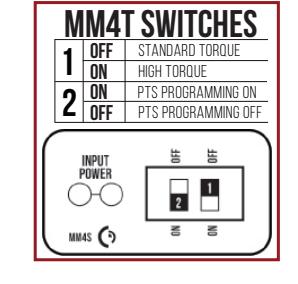
*Once you found your preferred adjustment, we recommend turning off the PTS programming switch.
TROUBLESHOOTING & DIAGNOSTICS
| BEEPS | EXPLANATION | SOLUTION |
|---|---|---|
| 2 Beeps | Over Voltage | > 30V unit will shut down. Check voltage & adjust to 24 V. |
| 3 Beeps | Under Voltage | < 20V unit will shut down. Check voltage & adjust to 24 V. |
| 4 Beeps | Failed Sensor | Verify all 3 sensor wires are installed correctly. Replace sensor if problem persists by contacting office. |
| 5 Beeps | Retraction or dogging failure | After 1st fail: 5 beeps then immediately attempts to retract again. After 2nd fail: 5 beeps with pause in-between for 30 seconds then device attempts to retract again. After 3rd fail: 5 beeps every 7 minutes, device will not attempt to retract. To Reset: Depress bar for 5 seconds at any time. |
| 6 Beeps | PUSH TO SET | Device is recording it's new position and power mode after the 6th beep. |
*TRIM POT ADJUSTMENT ONLY REQUIRED WHEN PTS PROGRAMMING IS NOT SETTING TO THE CORRECT LOCATION

*Latch bolt adjustment- If the latch bolt is not retracting far enough, turn the dial clockwise with a small flat blade screw driver. If the latch bolt is retracting too far causing the device to chatter and drop-out, turn the dial counter-clockwise until the chatter and drop-outs stop and the desired location is achieved.
installation instructions

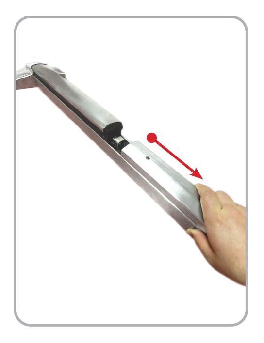
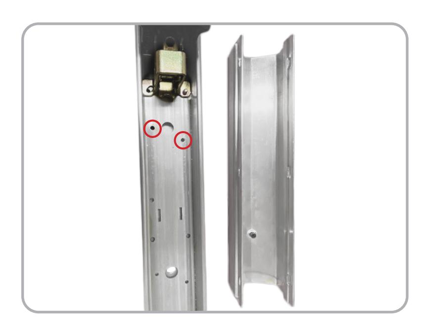
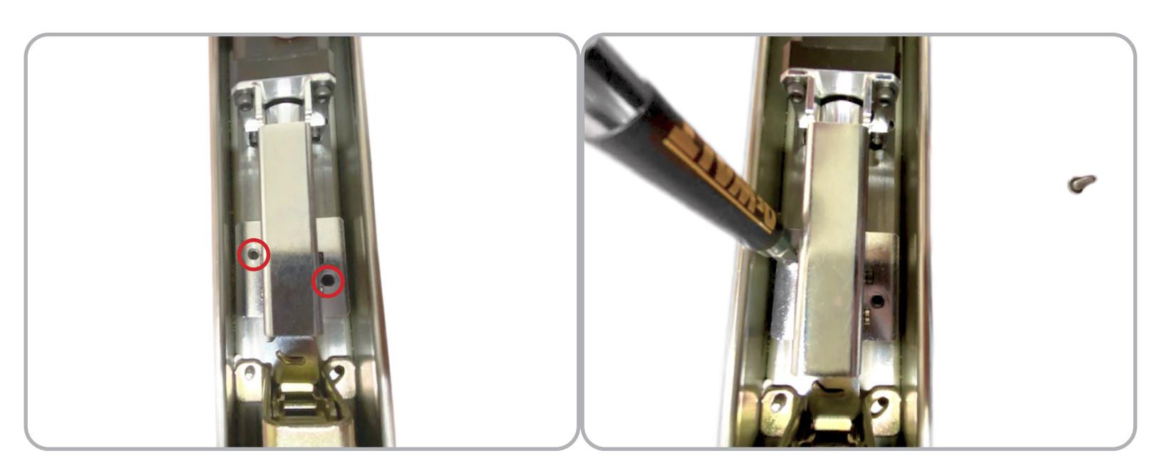
1 Remove Filler Plate 2 Remove Dogging Assembly if present (2 Phillips screws )
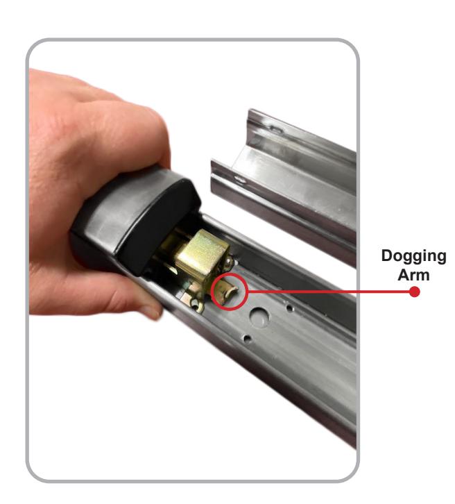
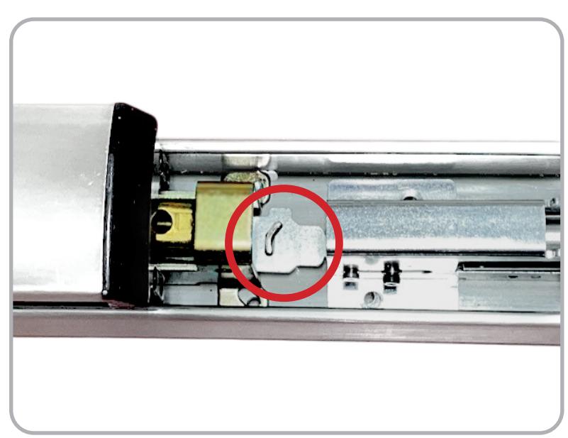
3 Depress Push Pad to expose Dogging Arm , line up cut out on Retraction Arm with tab on Exit Device .
installation instructions

4 Once in place pull back on the kit slightly to line up the mounting holes with the Exit Device's existing screw holes and install (2) Phillips mounting screws .
5 Connect to power and set the PTS adjustment by following the instructions on the next page.