MLRK1-CAL77-Insert-Instructions
Open the original PDF document
View PDF


MLRK1
I N S E R T I n s t r u c t i o n s
The Command Access MLRK1 is a field-installable motorized latch-retraction kit for:
- MLRK1-CAT25 Command Access PD26 series devices
- MLRK1-CAL77 Cal Royal 77 series devices

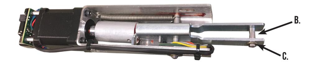


- 1 Motor Mount w/ MM4S series module A.
- 1 #50326 Link Pin B
- 2 #40145 Retaining Ring C.
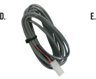
- 1- #50030 8' Lead with VD Connector D.
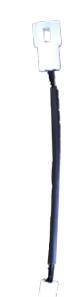
- 1 #50944 MM4S Socket Lead E.
- 1 #40144 Dogging Hole Cap F.
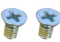
- 2 #40333 Phillips Head Screw G.
Kit Includes Tools Required
Cordless Drill Phillips head screwdriver
TECHNICAL INFORMATION

SPECIFICATIONS
Input Voltage: 24VDC +/- 10%Wire gauge: Minimum 18 gauge
Direct wire run - no relays or access control units in-between power supply & module
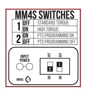
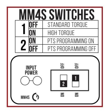
STANDARD TORQUE MODE
Average Latch Retraction Current: 900 mA Average Holding Current: 215 mA
HIGH TOROUE MODE
Average Latch Retraction Current: 2 Amp Average Holding Current: 250 mA
SETTING PTS

MAKE SURE TO SET PTS BEFORE FINISHING INSTALLATION
- STEP 1- Select your preferred torque mode (ships in standard torque) Press the device push pad to the desired setting. (Recommend to fully depress and release 5%, giving the device room for changing door conditions.)
- STFP 2- While depressing the push pad, apply power. (i.e. presenting the credential to the reader).
- STEP 3- Continue to keep pad depressed, the device will beep 6 times. After the beeps have stopped, release the pad and now the adjustment is complete. If not to your liking repeat the 3 steps.
- STFP 4- Once you found the correct location, turn PTS switch to OFF position.
TROUBLESHOOTING & DIAGNOSTICS
| BEEPS | EXPLANATION | SOLUTION |
|---|---|---|
| 2 Beeps | Over Voltage | > 30V unit will shut down. Check voltage & adjust to 24 V. |
| 3 Beeps | Under Voltage | < 20V unit will shut down. Check voltage & adjust to 24 V. |
| 4 Beeps | Failed Sensor | Verify all 3 sensor wires are installed correctly. Replace sensor if problem persists by contacting office. |
| 5 Beeps | Retraction or dogging failure | After 1st fail: 5 beeps then immediately attempts to retract again. After 2nd fail: 5 beeps with pause in-between for 30 seconds then device attempts to retract again. After 3rd fail: 5 beeps every 7 minutes, device will not attempt to retract. To Reset: Depress bar for 5 seconds at any time. |
| 6 Beeps | PUSH TO SET | Device is recording it's new position and power mode after the 6th beep. |
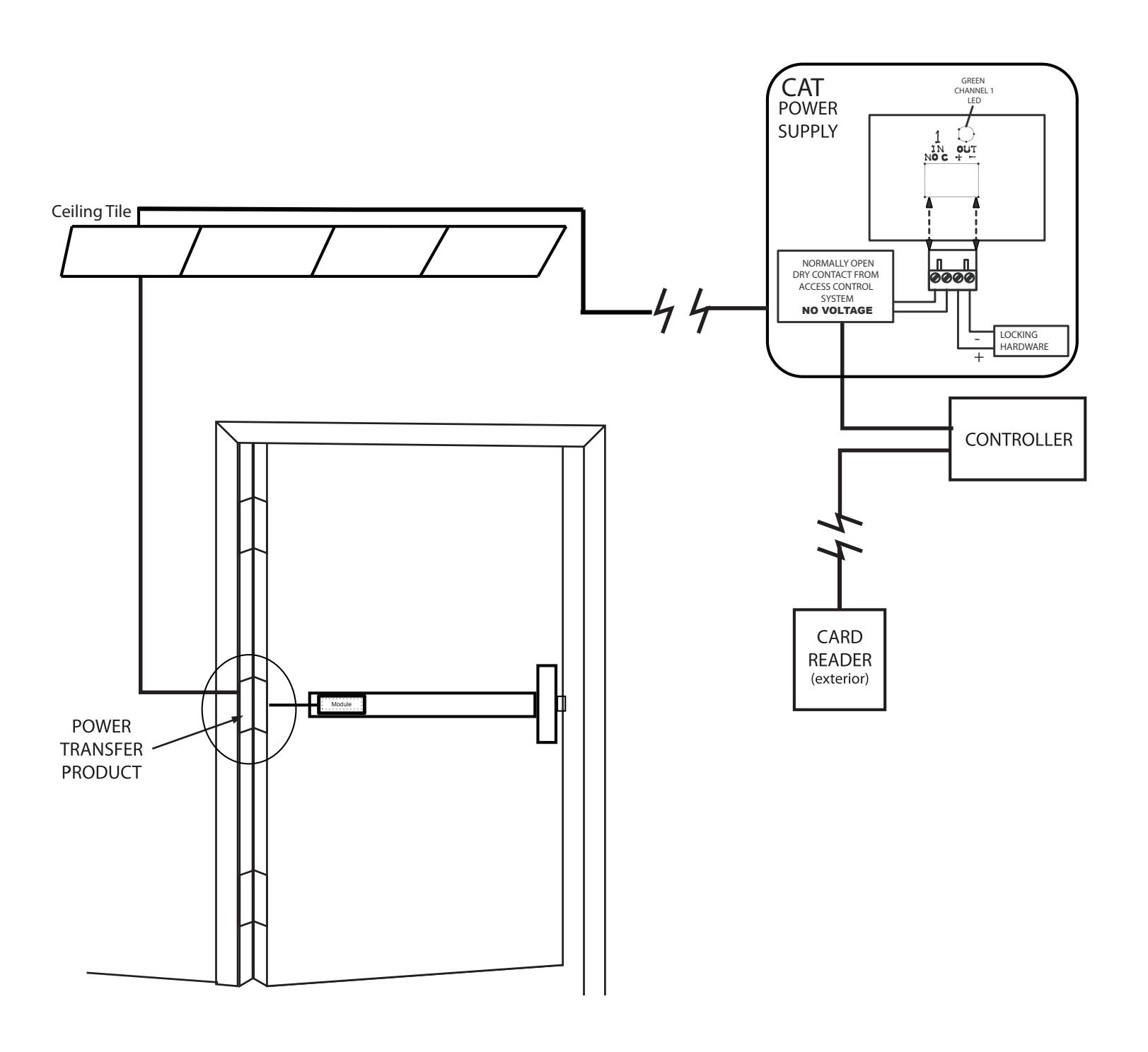
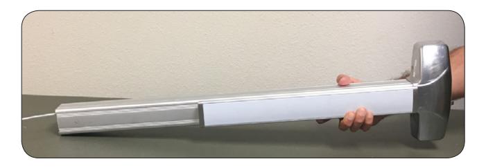
Electrified Exit Device

Installation Example
I n s ta l l at i o n I n s t r u c t i o n s

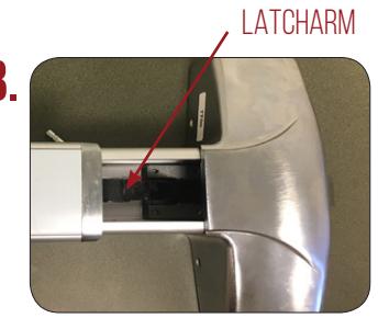
Un-dog push pad with dogging key found in box. 1.
Once loose, slide off back filler plate exposing dogging. 2.
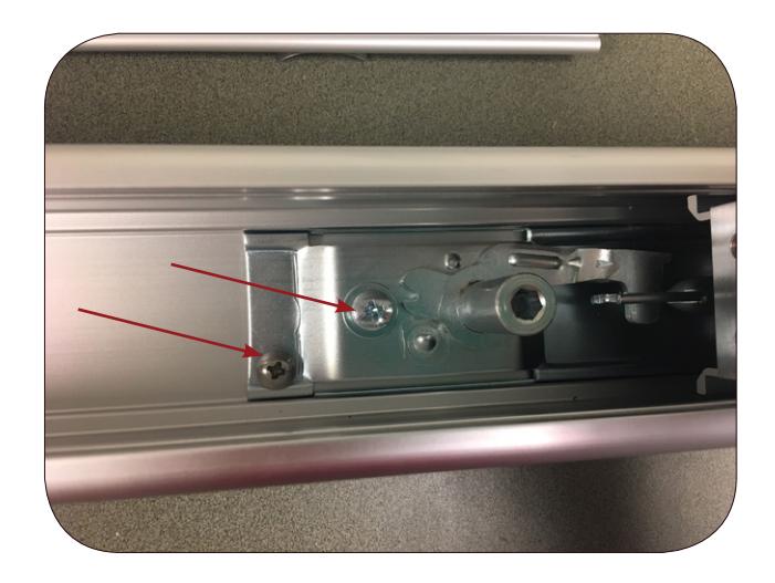
Loosen screws (2) and remove dogging bracket. 3.
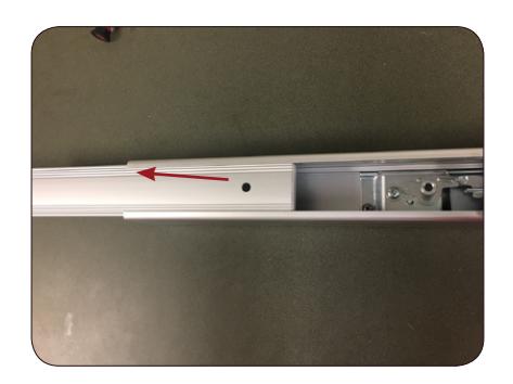
Once removed, slide push pad assembly out the 4. back of the device.
5. When top push pad is removed, flip the device over and remove dogging screw.
I n s ta l l at i o n I n s t r u c t i o n s

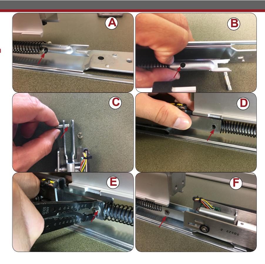
- 6. Remove roll pin from back of connecting rod by detaching "C" clip from either side.(A) Remove pin completely. (B)
- 7. Remove roll pin from kit (C) and line up holes with device holes. (D)
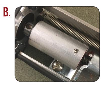
8. Push roll pin through kit and device holes and attach "C" clips. (E) Once attached, motor should be secure. (F)
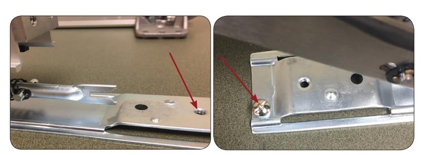
Once the kit is secure with the pin, lift up and insert back screw into the bottom dogging hole. Do not tighten until device is assembled. 9.
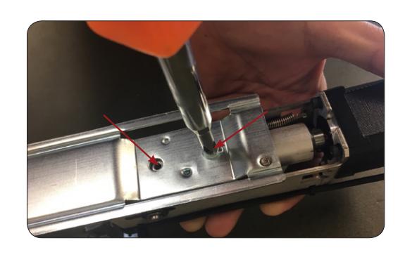
10. Once kit is connected, flip device over and put screws back in dogging holes.
INSTALLATION INSTRUCTIONS

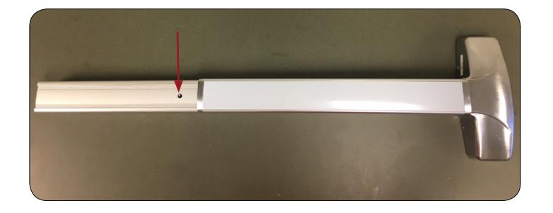
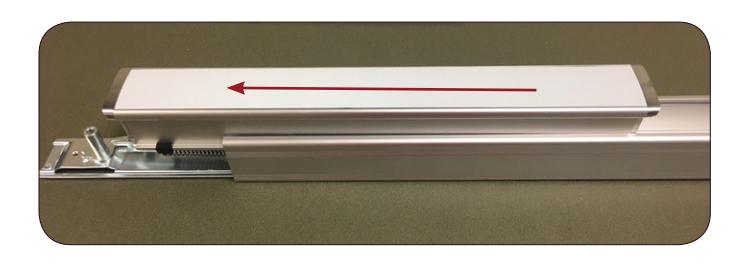
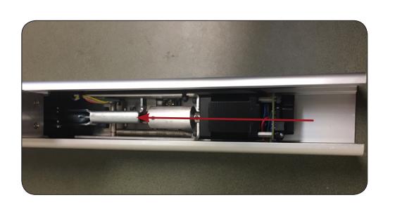
11. Flip back over and slide push pad with motor back into exit device.

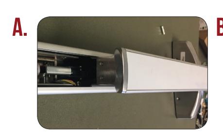
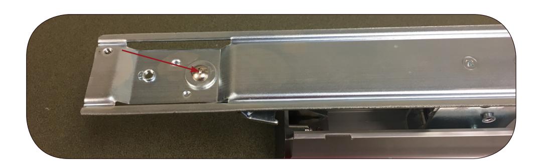
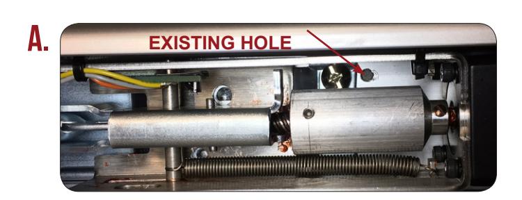
Once push pad is back inside device and the screw lines up with existing hole, (A) tighten back screw to hold motor in place.(B)
14. Slide filler plate back into place. Connect to power supply to test and set PTS position using the instructions below, remembering to turn the Programming Switch to the off position when completed.
SETTING PTS
- STEP 1- Select your preferred torque mode (ships in standard torque) Press the device push pad to the desired setting. (Recommend to fully depress and release 5%, giving the device room for changing door conditions.)
- STFP 2- While depressing the push pad, apply power. (i.e. presenting the credential to the reader).
- STEP 3- Continue to keep pad depressed, the device will beep 6 times. After the beeps have stopped, release the pad and now the adjustment is complete. If not to your liking repeat the three steps
- STEP 4- Once you found the correct location, flip the dip switches to off to lock programming.