MLRK1-AREX_Insert-Instruction
Open the original PDF document
View PDF


mlrk1
INSERT INSTRUCTIONS
The Command Access MLRK1 is a field installable motorized latch-retraction kit for: • MLRK1-AREX - Adams Rite EX series devices
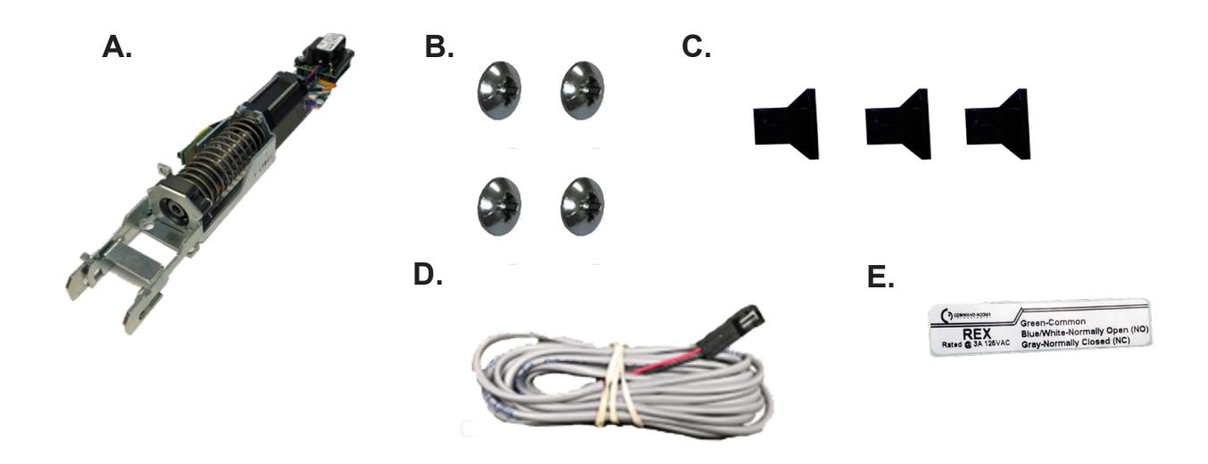
KIT INCLUDES | TOOLS REQUIRED
- A. Motor Kit
- B. 4 - Phillips Head Screws
- C. 3 - Wire clips
- D. 1 - 8' Lead
- E. Optional REX (if ordered)
- • Cordless Drill or Phillips Screwdriver
- • Power Source

Technical Information

SPECIFICATIONS
POWER
- Input Voltage: 24VDC +/- 10%Wire gauge: Minimum 18 gauge
- Direct wire run no relays or access control units inbetween power supply & module
Request to Exit
- Single Pole Double Throw (SPDT)
- Rating: .5A @24VAC
- Configuration: Green Common (C)
Blue - Normally Open (NO) Gray - Normally Closed (NC)
Standard Torque Mode
Average Latch Retraction Current: 1.3 A Average Holding Current: 215 mA
High Torque Mode
Average Latch Retraction Current: 2 Amp Average Holding Current: 250 mA
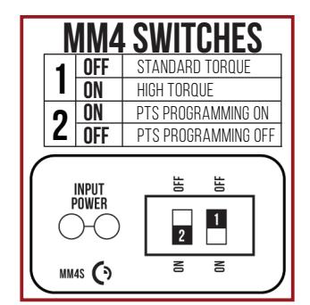
Setting PTS →**Important Info** ----------------------------------
Make sure to set PTS before finishing installation
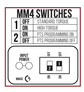
- Step 1- Select your preferred torque mode (ships in standard torque) Press the device push pad to the desired setting. (Recommend to fully depress and release 5%, giving the device room for changing door conditions.)
- Step 2- While depressing the push pad, apply power. (i.e. presenting the credential to the reader).
- Step 3- Continue to keep pad depressed, the device will beep 6 times. After the beeps have stopped, release the pad and now the adjustment is complete. If not to your liking repeat the 3 steps.
- Step 4- Once you found the correct location, turn PTS switch to OFF position.
TROUBLESHOOTING & DIAGNOSTICS
| BEEPS | EXPLANATION | SOLUTION |
|---|---|---|
| 2 Beeps | Over Voltage | > 30V unit will shut down. Check voltage & adjust to 24 V. |
| 3 Beeps | Under Voltage | < 20V unit will shut down. Check voltage & adjust to 24 V. |
| 4 Beeps | Failed Sensor | Verify all 3 sensor wires are installed correctly. Replace sensor if problem persists by contacting office. |
| 5 Beeps | Retraction or dogging failure | After 1st fail: 5 beeps then immediately attempts to retract again. After 2nd fail: 5 beeps with pause in-between for 30 seconds then device attempts to retract again. After 3rd fail: 5 beeps every 7 minutes, device will not attempt to retract. To Reset: Depress bar for 5 seconds at any time. |
| 6 Beeps | PUSH TO SET | Device is recording it's new position and power mode after the 6th beep. |
Electrified Exit Device
Installation Example

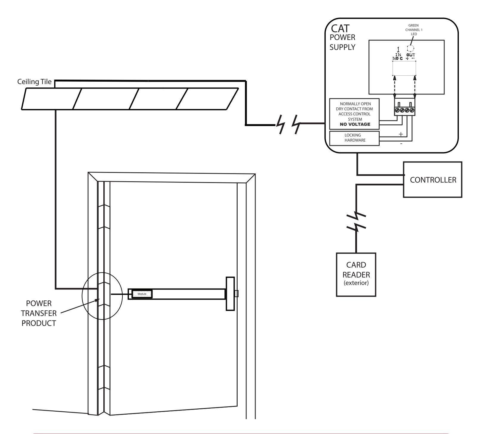
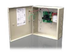
Recommended Power Supplies:
All Command Access exit devices & field installable kits have been thoroughly cycle tested with Command Access power supplies at our factory.

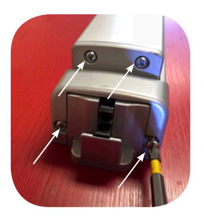
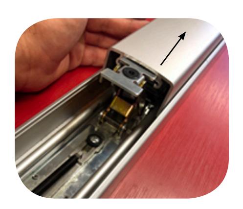
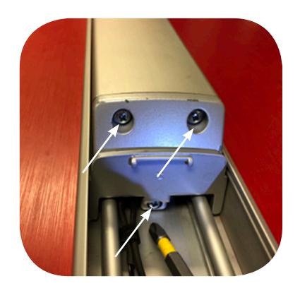
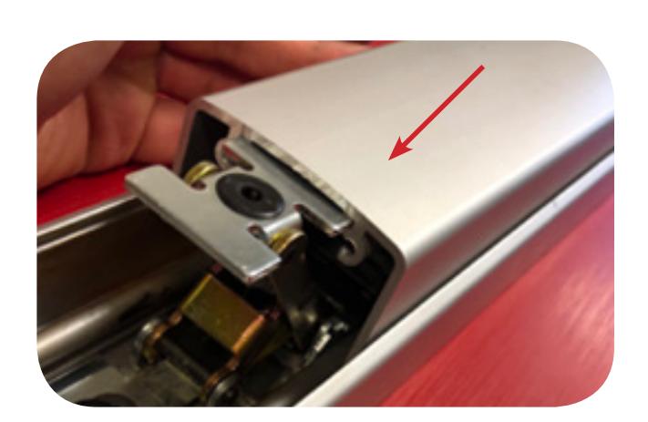
1. Remove head cover & front push pad end cap.
3. Slide off push pad
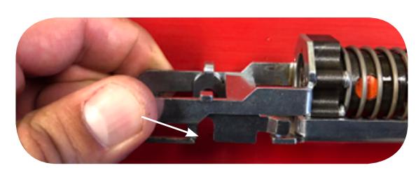
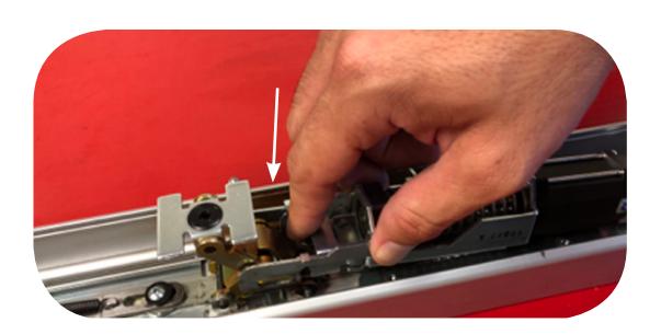
Grab motor kit make sure magnet bracket is all the way back. The hooks will be open to drop over activiting bracket pin. 5.
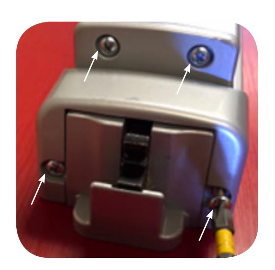
2. Remove both back push pad end caps
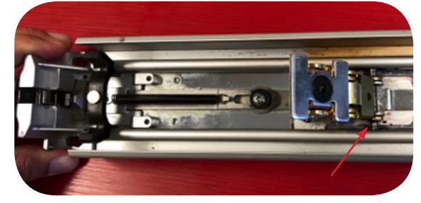
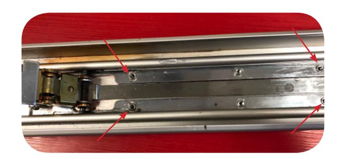
Remove dogging if present. Motor kit will line up with existing front & back screw holes & hooks onto the front activitating bracket. 4.
Install front of the motor kit with the hooks dropping over roll pin. 6.
Installation Instructions
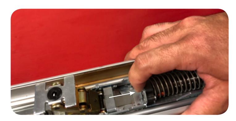
- Once the kit is on the roll pin pull back to look them into place. 7.
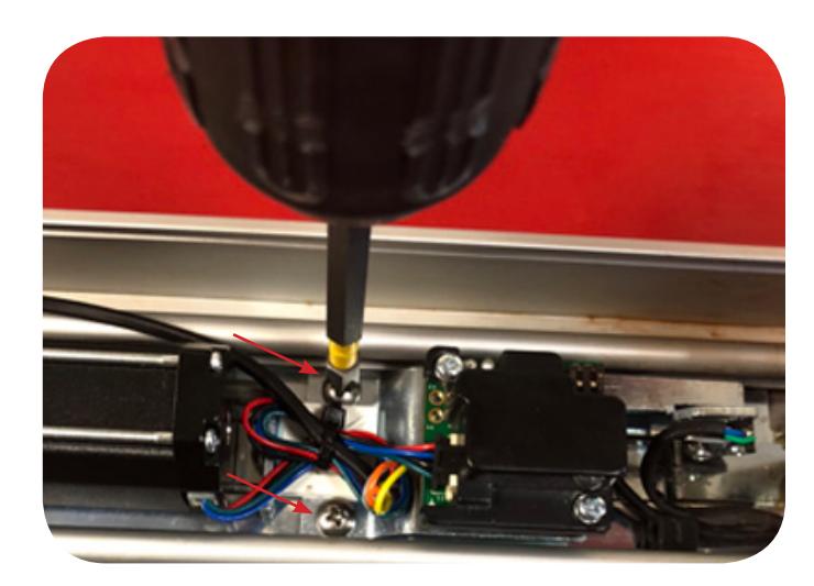
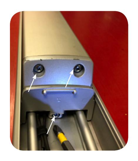
- Line up front set of screw holes with exisiting holes & install (2) screws provided. 8.
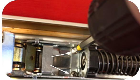
- Line up back set of screw holes with exisiting holes & install (2) scews provided; 9.
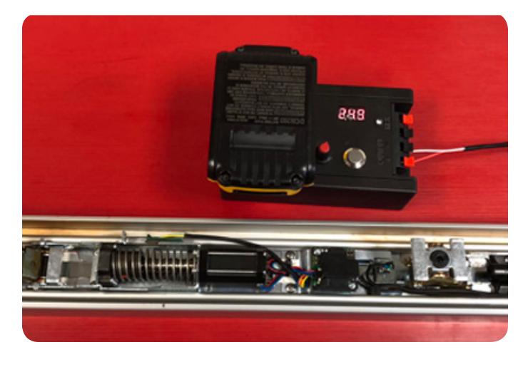
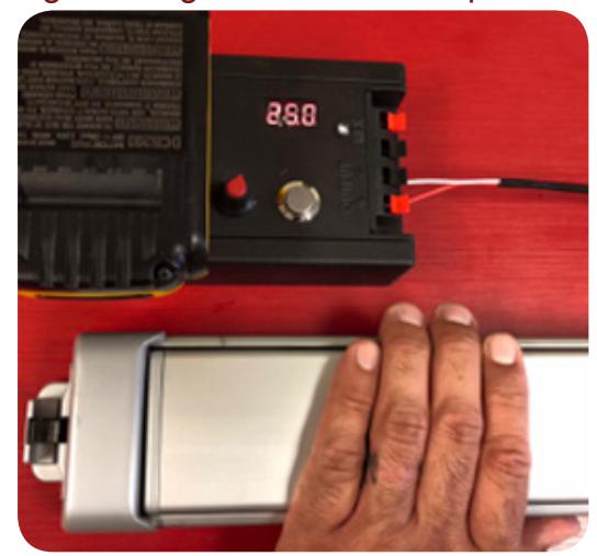
- Hook up to power to test motor before re-assembling device. 10.
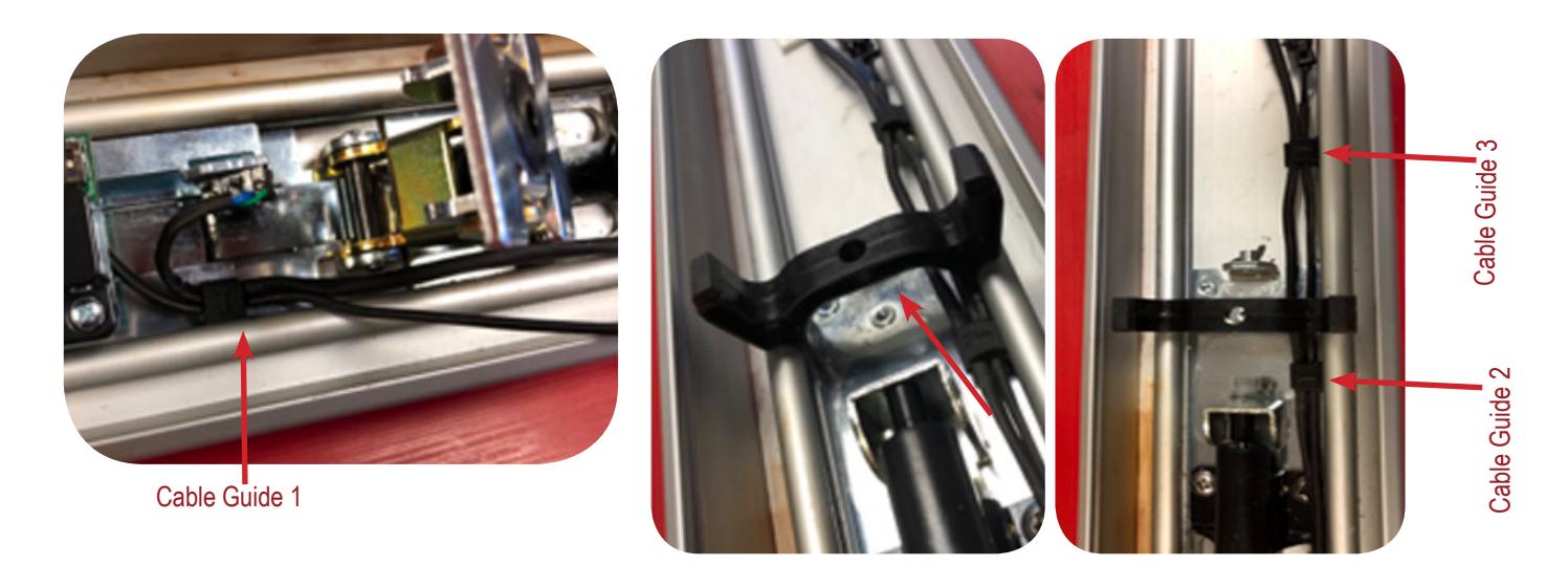
11. Attach Cable guides by pressing them into middle channel. Side maked T should face up.
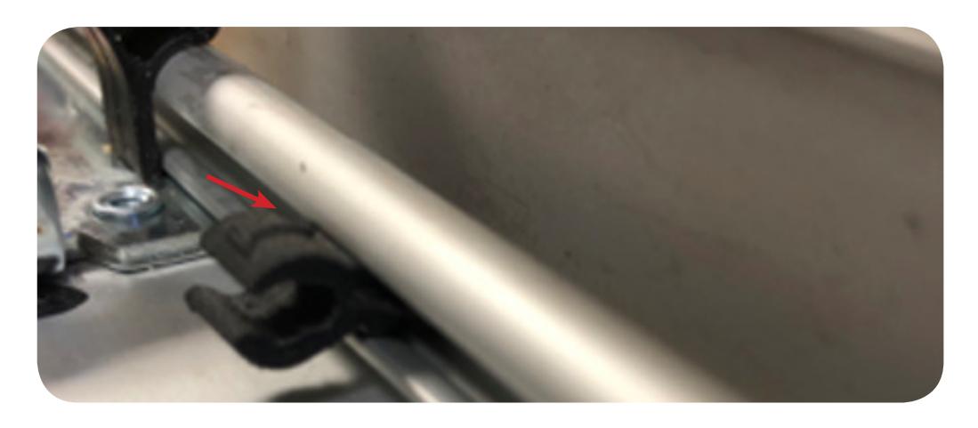

12. Attach the cable guides and then press wires into guides.
13. Slide the pushpad back onto the device
14. Re-install the both front end caps.

15. Re-install both back activiating brackets.
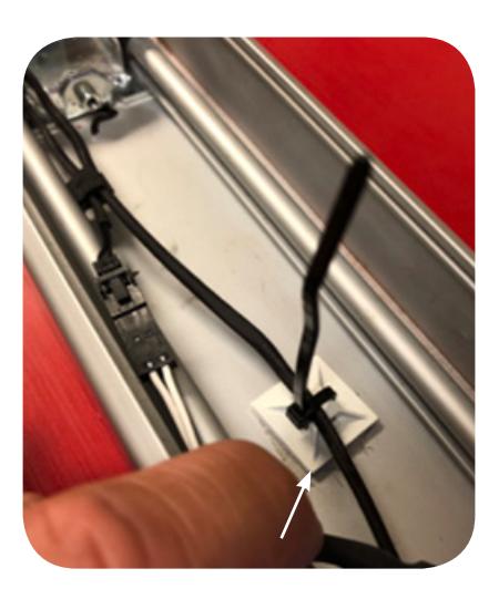
16. If you have the REX, add sticky pad with zip tie as a strain relief.
17. Next, hook up to power and set the Push-to-Set adjustment, remembering to turn the Programming Switch to the off position when completed.
Setting PTS → **Important Info** ◄
Make sure to set PTS before finishing installation
- Step 1- Select your preferred torque mode (ships in standard torque) Press the device push pad to the desired setting. (Recommend to fully depress and release 5%, giving the device room for changing door conditions.)
- Step 2- While depressing the push pad, apply power. (i.e. presenting the credential to the reader).
- Step 3- Continue to keep pad depressed, the device will beep 6 times. After the beeps have stopped, release the pad and now the adjustment is complete. If not to your liking repeat the 3 steps.
- Step 4- Once you found the correct location, turn PTS switch to OFF position.