MLRK1-AR-Insert-Instructions
Open the original PDF document
View PDF


MLRK1
I N S E R T I n s t r u c t i o n s
The Command Access MLRK1 is a field installable motorized latch-retraction kit for: • MLRK1-AR - Adams Rite 82/84/86/88 series devices
NOTE: Our kit is designed to work with devices manufactured after 2003 due to changes in the exit device housing. If you try to install our kit in an older device (pre-2003) it will take significant modification. For any questions please contact the factory.
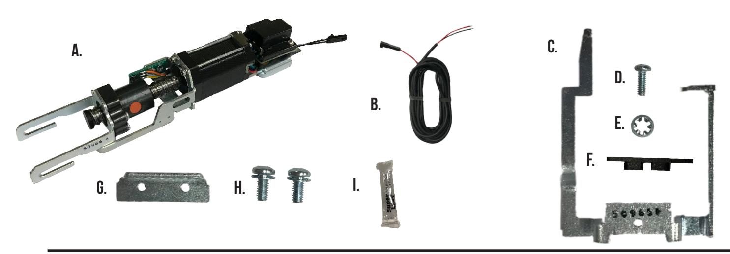
Kit Includes
- A. 60199 mlrk1-ar
- B. 50436 8' power lead
- C. 50965 magnet bracket
- D. 40812 phillips screw
- E. 40813 lock washer
- F. 50990 screw shim
- G. 50799 hold down bracket
- H. 40771 phillips screw w/washer x2
- I. 40393 super lube
Tools Required
#1 and #2 phillips screwdriver
SPECIFICATIONS Standard Torque Mode
- Input Voltage: 24VDC +/- 10% • Wire gauge: Minimum 18 gauge
- Direct wire run no relays or access control units in-between power supply & module
Average Latch Retraction Current: 1.3 Amp Average Holding Current: 215 mA
High Torque Mode
Average Latch Retraction Current: 2 Amp Average Holding Current: 250 mA
Recommended Power Supplies:
All Command Access exit devices & field installable kits have been thoroughly cycle tested with Command Access power supplies at our factory. If you plan on using a non-Command power supply it must be a filtered & regulated linear power supply.
TECHNICAL INFORMATION

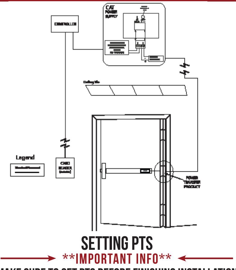

MAKE SURE TO SET PTS BEFORE FINISHING INSTALLATION
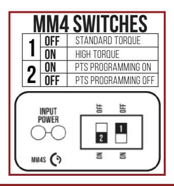
- STEP 1 - Select your preferred torque mode (ships in standard torque). Press the device push pad to the desired setting. (We recommend to fully depress and release 5%, giving the device room for changing door conditions.)
- STEP 2 While depressing the push pad, apply power. (i.e. presenting the credential to the reader).
- STEP 3 Continue to keep the pad depressed, the device will beep 6 times. After the beeps have stopped, release the pad and the adjustment is now complete. If not to your liking repeat the 3 steps.
TROUBLESHOOTING & DIAGNOSTICS
| BEEPS | EXPLANATION | SOLUTION |
|---|---|---|
| 2 Beeps | Over Voltage | > 30V unit will shut down. Check voltage & adjust to 24 V. |
| 3 Beeps | Under Voltage | < 20V unit will shut down. Check voltage & adjust to 24 V. |
| 4 Beeps | Failed Sensor | Verify all 3 sensor wires are installed correctly. Replace sensor if problem persists by contacting office. |
| 5 Beeps | Retraction or dogging failure | After 1st fail: 5 beeps then immediately attempts to retract again. After 2nd fail: 5 beeps with pause in-between for 30 seconds then device attempts to retract again. After 3rd fail: 5 beeps every 7 minutes, device will not attempt to retract. To Reset: Depress bar for 5 seconds at any time. |
| 6 Beeps | PUSH TO SET | Device is recording it's new position and power mode after the 6th beep. |
installation instructions

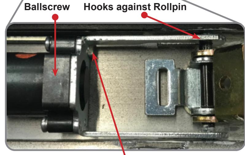
1 Lay the MLRK1-AR down and adjust the Ballscrew so it is behind the Retaining Arm Stop, leaving a small gap between the Ballscrew and Overtravel Cap .
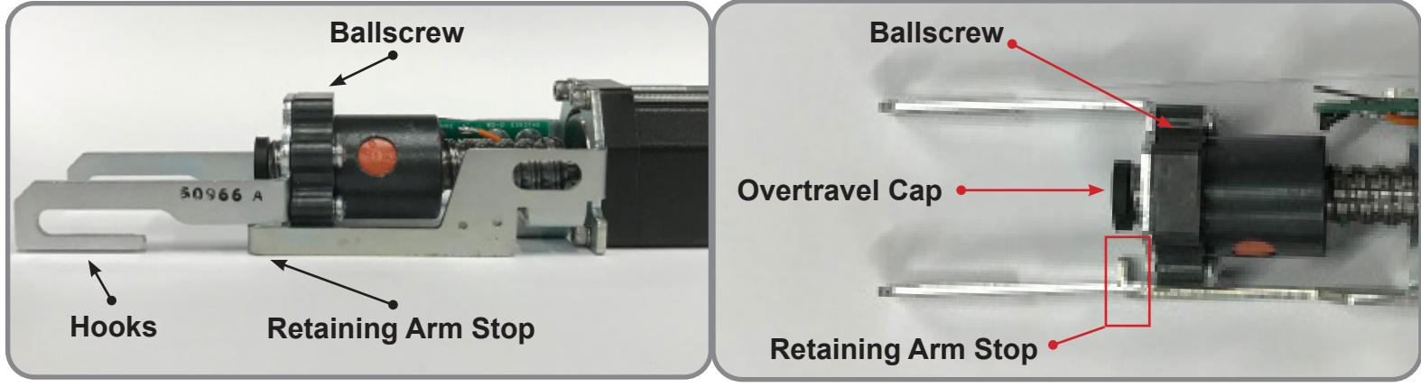
* Note that the Hooks on the Ballscrew Bracket will be referenced in Step 3.
2 Depress and hold down the Activating Scissor Brackets to drop in the Kit.
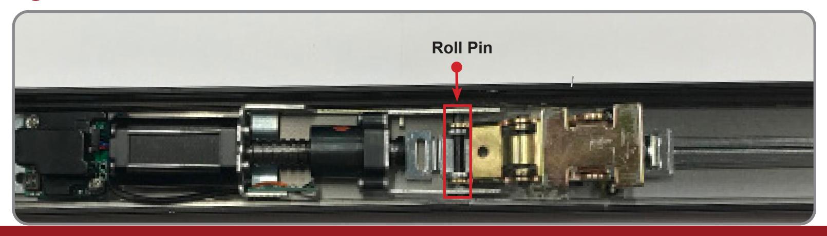
3 Install the Kit into the back of the Exit Device, ensuring it is laying completely flat and the Ballscrew Hooks are in front of the Device Roll Pin .
INSTALLATION INSTRUCTIONS

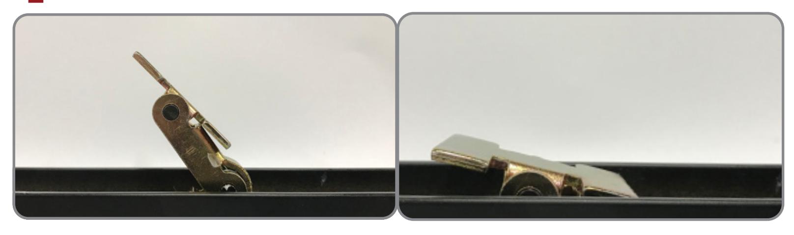
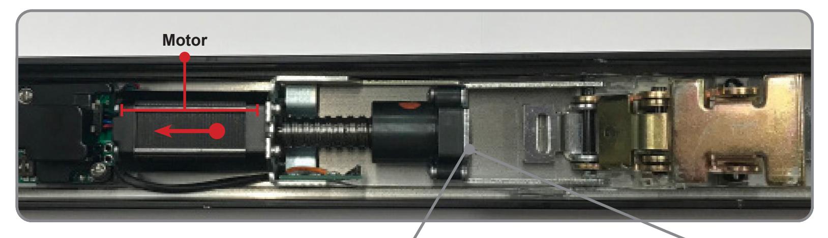
Release the Activating Scissor Brackets, gently pull the Kit back by the Motor until the Ballscrew is touching the Retaining Arm Stop . (See Figure 4.A)
4. A
* The MLRK1-AR's position shown in 4.A shows the correct position for the Hooks and the Retaining Arm Stop.
Retaining Arm Stop
G. •
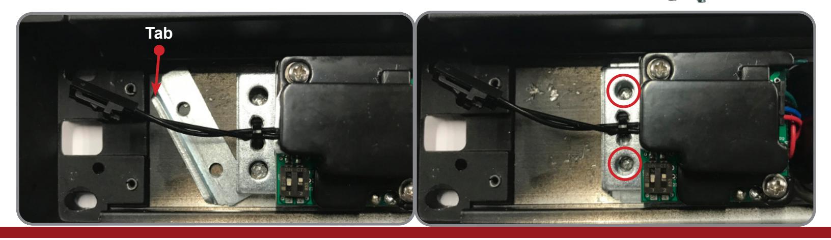
Position the Hold Down Bracket (50799) with the Tab facing up and to the back of the device, then slide it under the Kit until the holes align. While gently pulling on the motor to keep the Kit in position screw in the two Phillips Screws with Lock Washers (40771) and tighten.
INSTALLATION INSTRUCTIONS

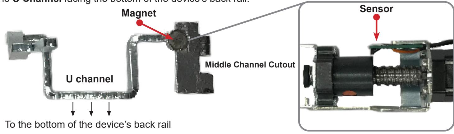
Before installing the Magnet Bracket (50965) apply a light coating of Super Lube (40393) to The Middle Channel Cutout . To place the bracket correctly, align the Magnet to the Kit's Sensor with the U Channel facing the bottom of the device's back rail.
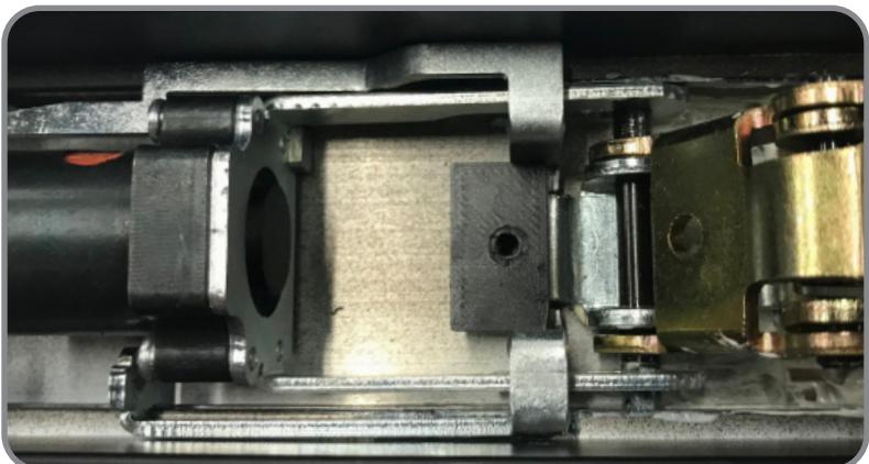
Install the Magnet Bracket (50965) at an angle, allowing the Middle Channel Cutout to ride on the Back Rail Extrusion (See picture 1). Push the Bracket down and when seated properly it should be below the Device's Activating Linkage (See picture 2).
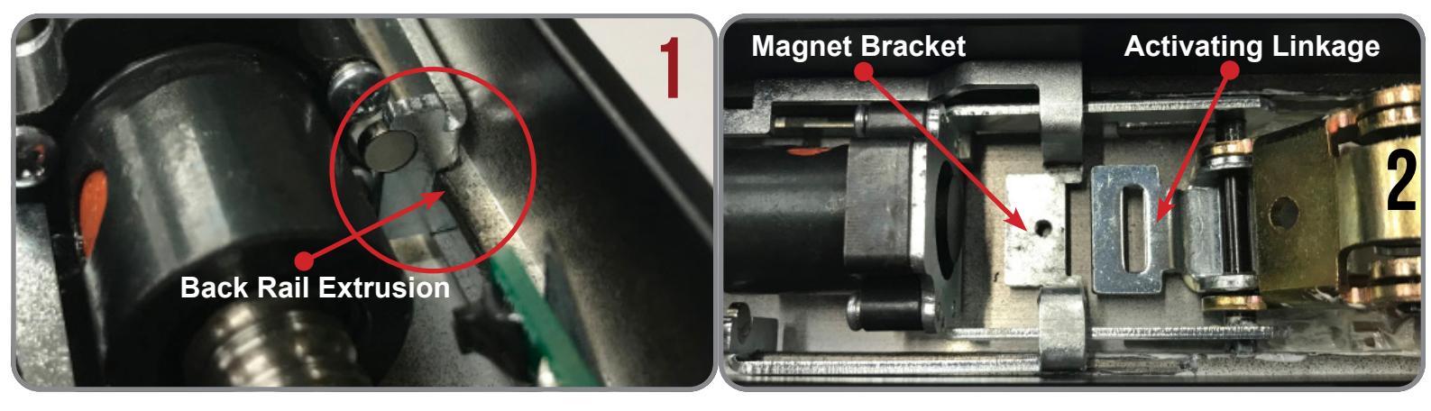
Slide the Magnet Bracket (50965) forward and under the Activating Linkage . The Screw Shim (50990) has Raised Guides that must be installed downwards into the Activating Linkage .
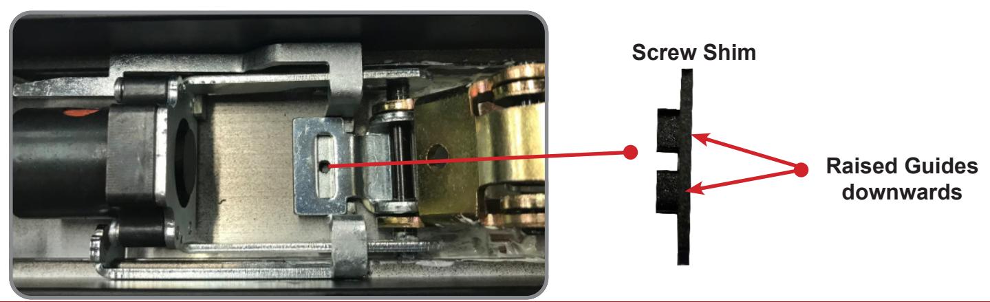
INSTALLATION INSTRUCTIONS

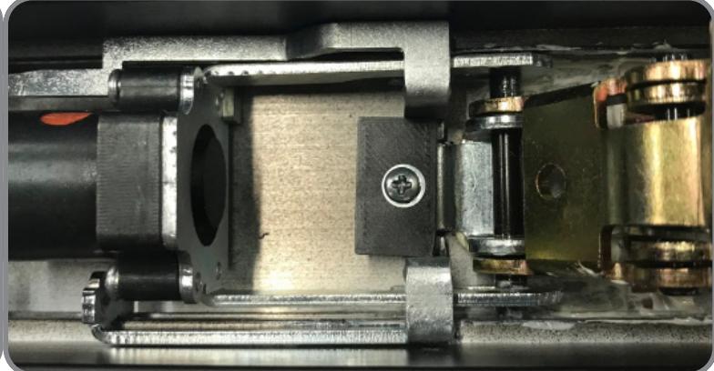
Push the Screw Shim (50990) into the Activating Linkage then install the Phillips Screw (40812) and Lock Washer (40813). * HAND TIGHTEN ONLY *
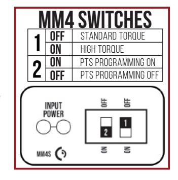
Connect the MLRK1-AR to power and follow the Push To Set instructions below, remembering to turn the Programming Switch to the off position when completed.
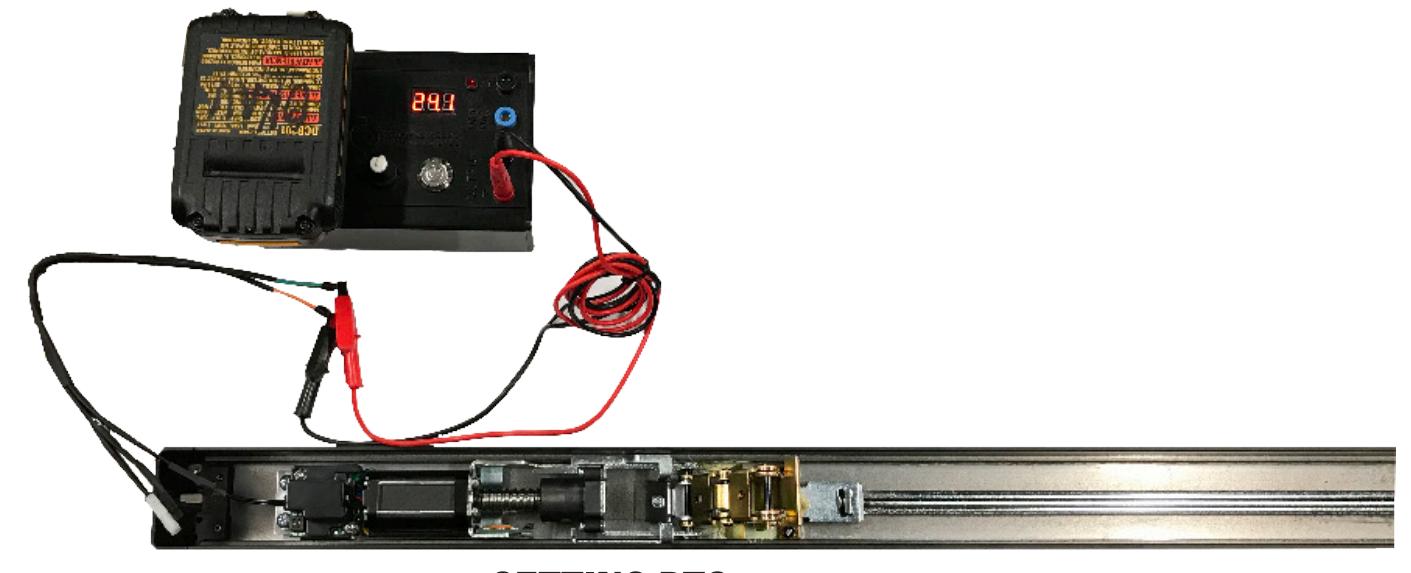
SETTING PTS * MAKE SURE TO SET PTS BEFORE FINISHING INSTALLATION *
- STEP 1 - Select your preferred torque mode (ships in standard torque). Press the device push pad to the desired setting. (We recommend to fully depress and release 5%, giving the device room for changing door conditions.)
- STEP 2 - While depressing the push pad, apply power. (i.e. presenting the credential to the reader).
- STEP 3 Continue to keep the pad depressed, the device will beep 6 times. After the beeps have stopped, release the pad and the adjustment is now complete. If not to your liking repeat the 3 steps.