ML80-CAT-Insert-Instructions-1
Open the original PDF document
View PDFINSTALLATION INSTRUCTIONS
ML70/80/82/480/485
Schlage Lock modified by Command Access Technologies

STEP 1 : The door must be machined with a 3/8" wire raceway, mortise lock pocket & prepped for a energy transfer hinge. Make sure the mortise pocket is free of debris.
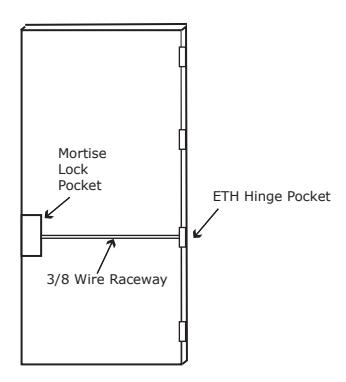
STEP 2 : Run the wires from the ETH hinge through the 3/8" raceway starting at the ETH hinge & exiting into the mortise pocket.
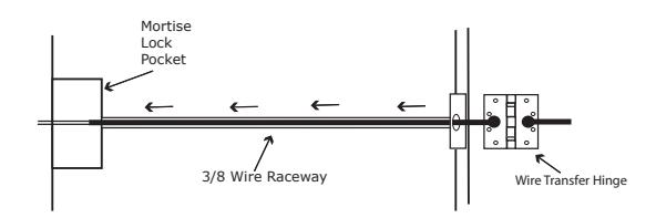
STEP 3: Screw the ETH hinge to the door. At this time DO NOT connect the hinge wires on the jamb side to the wires coming from the power supply.
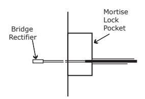
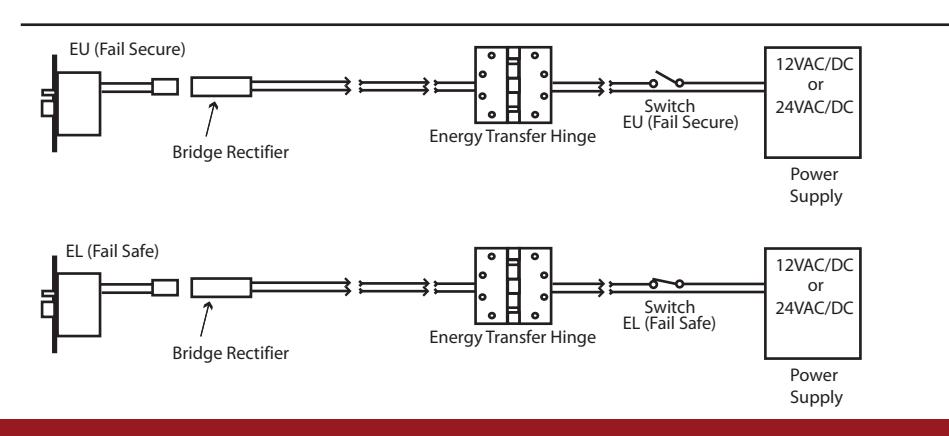
STEP 4: Connect the wires exiting the mortise pocket to the Bridge Rectifier (included).
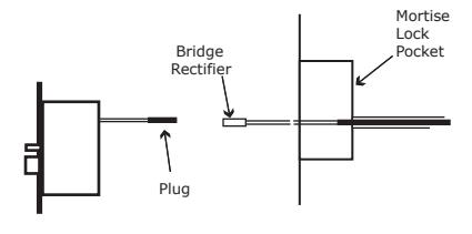
STEP 5 : Connect the Bridge Rectifier to the plug exiting the mortise chassis.
STEP 6 : Carefully slip the connected mortise lock chassis into the mortise pocket paying close attention not to pinch any wires.
STEP 7 : Mount the chassis per manufacturer's instructions.
STEP 8 : Connect the wires from the power supply at the ETH hinge on the jamb side. Connect the hinge to the jamb.
LEGEND OF TERMS
EU: (Fail Secure) When power is applied, the outside trim will unlock. When power is removed, the outside trim is locked.
*EL: (Fail Safe) When power is applied, the outside trim will lock. When power is removed, the outside trim is unlocked.
REX: (Request to Exit Switch) Monitors the inside and outside handles.
DPS: (Door Position Switch) Monitors the door position via the anti pick (Deadlatch).
LBM: (Latchbolt Monitor Switch) Monitors the position of latchbolt.
* Not Available in all locks
ELECTRICAL SPECIFICATIONS
SOLENOIDS:
VOLTS CURRENT COIL RESISTANCE 24VAC/DC 350mA 69 Ohms +/- 10% 12VAC/DC 700mA 18 Ohms +/- 10%
SWITCHES: . 5A 24VAC/DC
REX : Green - Common (C)
Blue - Normally Open (NO) Gray - Normally Closed (NC)
LBM : Green/Black - Common (C)
Blue/Black - Normally Open (NO) Gray/Black - Normally Closed (NC)
DPS : White - Common (C)
Blue - Normally Open (NO) Black - Normally Closed (NC)
DBM : Green - Common (C)
Blue/Black - Normally Open (NO) Gray/Black - Normally Closed (NC)
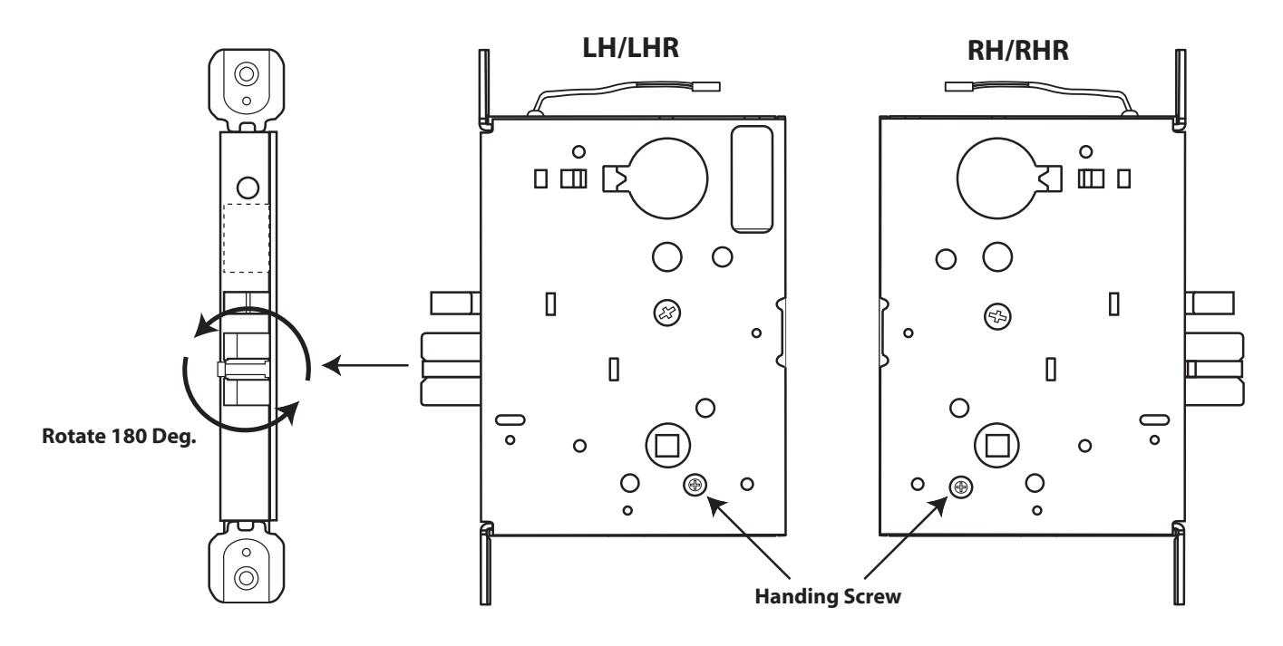
Handing Instructions for ML70/80/82/480/485 Mortise Locks
STEP 1 : Locate the handing screw. This screw is used to hand the handles. The Locking side is opposite the screw.
STEP 2 : To hand the latchbolt, remove the faceplate. Pull the latchbolt out of the chassis and rotate, then release. The latchbolt is spring loaded and will return on it's own.
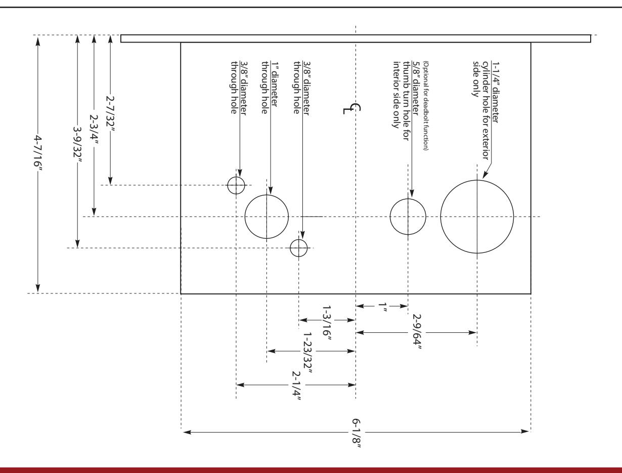
Template for ML70/80/82/480/485 Mortise Locks
INSTRUCTIONS TO SET FUNCTION FAIL SAFE OR FAIL SECURE FOR ALL ML70/80/82/480/485 LOCKS
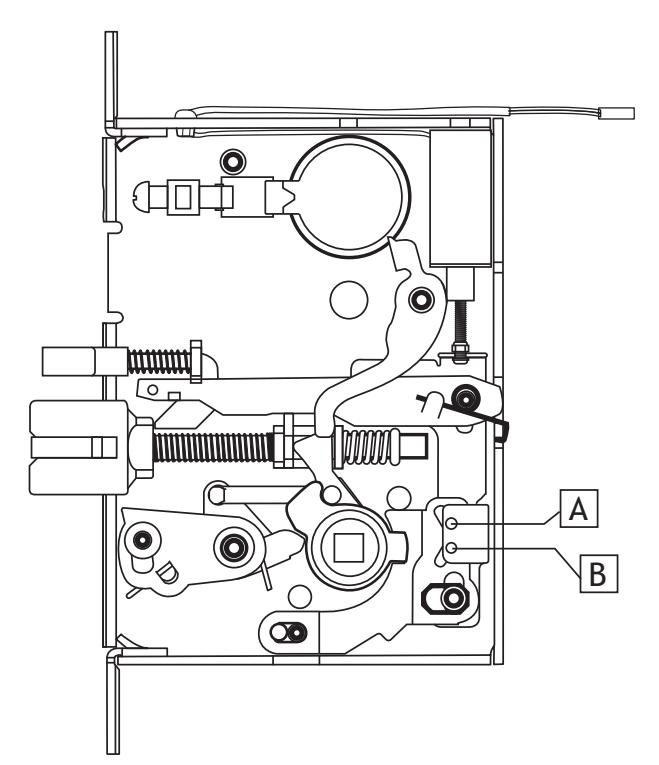
- STEP 1: Remove the (4) Phillips head screws holding on the cover.
- STEP 2: Locate the holes "A" & "B" in the illustration.
- STEP 3: Remove the metal pin with a magnetized screw driver. Make sure the pin is completely seated when re-inserted in either hole "A" or "B".
- STEP 4 : Be careful to make sure the solenoid remains in the correct position in the machined cavity in the cover. Re-install the cover with the 4 screws previously removed. The cover should lay flat on the lock chassis. If not, check to see if the lock parts are seated correctly in the chassis.


*** We recommend that this procedure be done by someone having experience with mortise locks ***