ML-37 SAR-Install-Instructions
Open the original PDF document
View PDFINSTALLATION INSTRUCTIONS ML370/371/372/373/336/337
Sargent Lock modified by Command Access Technologies

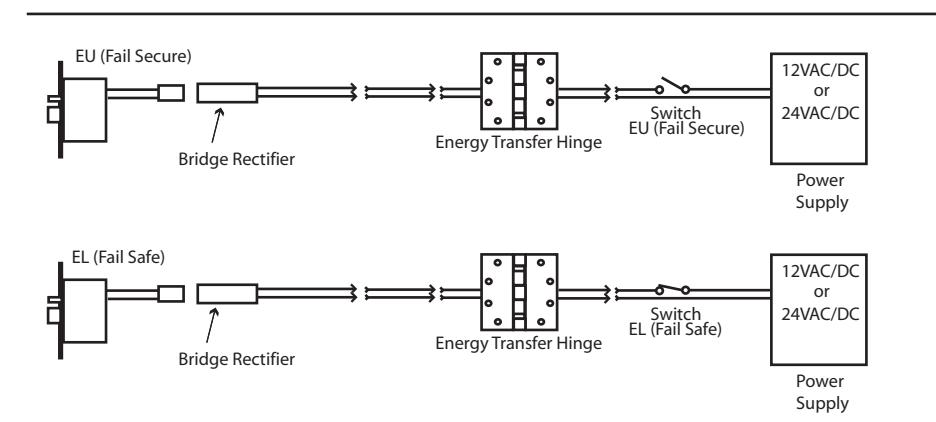
STEP 1 : The door must be machined with a 3/8" wire raceway, mortise lock pocket & prepped for a energy transfer hinge. Make sure the mortise pocket is free of debris.
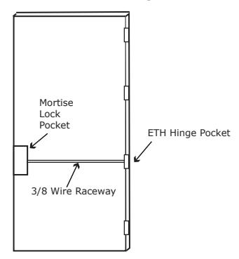
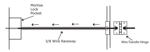
STEP 2 : Run the wires from the ETH hinge through the 3/8" raceway starting at the ETH hinge & exiting into the mortise pocket.
STEP 3 : Screw the ETH hinge to the door. At this time DO NOT connect the hinge wires on the jamb side to the wires coming from the power supply.
STEP 4 : Connect the wires exiting the mortise pocket to the Bridge Rectifier (included).
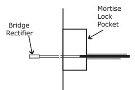
STEP 5 : Connect the Bridge Rectifier to the plug exiting the mortise chassis.
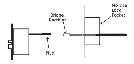
STEP 6 : Carefully slip the connected mortise lock chassis into the mortise pocket paying close attention not to pinch any wires.
STEP 7 : Mount the chassis per manufacturer's instructions.
STEP 8 : Connect the wires from the power supply at the ETH hinge on the jamb side. Connect the hinge to the jamb.
LEGEND OF TERMS
EU : (Fail Secure) When power is applied, the outside trim will unlock. When power is removed, the outside trim is locked.
EL : (Fail Safe) When power is applied, the outside trim will lock. When power is removed, the outside trim is unlocked.
REX : (Request to Exit Switch) Monitors the inside handle.
DPS : (Door Position Switch) Monitors the door position via the anti pick (Deadlatch).
LBM : (Latchbolt Monitor Switch) Monitors the position of latchbolt.
ELECTRICAL SPECIFICATIONS
SOLENOIDS:
VOLTS CURRENT COIL RESISTANCE 24VAC/DC 350mA 69 Ohms +/- 10% 12VAC/DC 700mA 18 Ohms +/- 10%
SWITCHES: . 25A 24VAC/DC
REX: Green -Common (C) (LH/LHR) Blue -Normally Open (NO) Gray -Normally Closed (NC)
REX: Green/White -Common (C) (RH/RHR) Blue/White -Normally Open (NO) Gray/White -Normally Closed (NC)
LBM : Green/Black -Common (C)
Blue/Black -Normally Open (NO) Gray/Black -Normally Closed (NC)
DPS : Green/Red -Common (C)
Blue/Red -Normally Open (NO) Gray/Red -Normally Closed (NC)
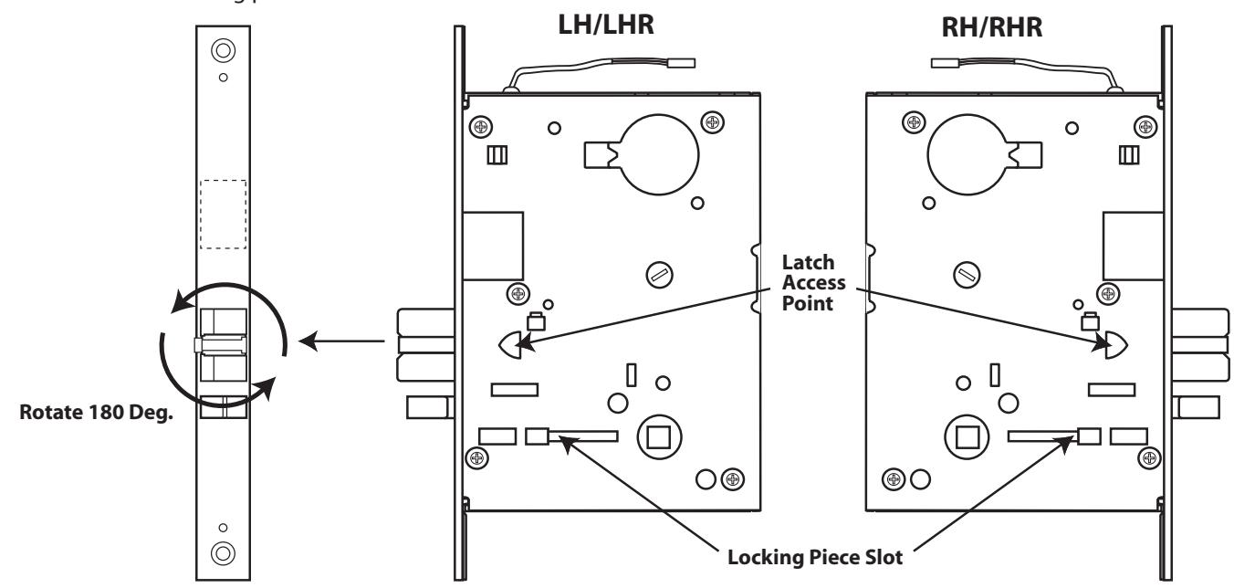
Handing Instructions for ML370/371/372/373/336/337 Mortise Locks
- STEP 1 : To rotate the latchbolt, insert a blade screwdriver into the latch access point and rotate 90° to push latch out until back of latch clears front of lock. Then rotate latch 180°. Latch will then retract into the case.
- STEP 2 : To rotate locking piece, position the lock body with the RED surface of locking piece visible.
- STEP 3 : Insert blade screwdriver into locking piece slot to rotate locking piece.
- STEP 4 : Push locking piece toward back of lock body and rotate 180 until RED surface shows on opposite side. NOTE: RED color indicates locked side of door.
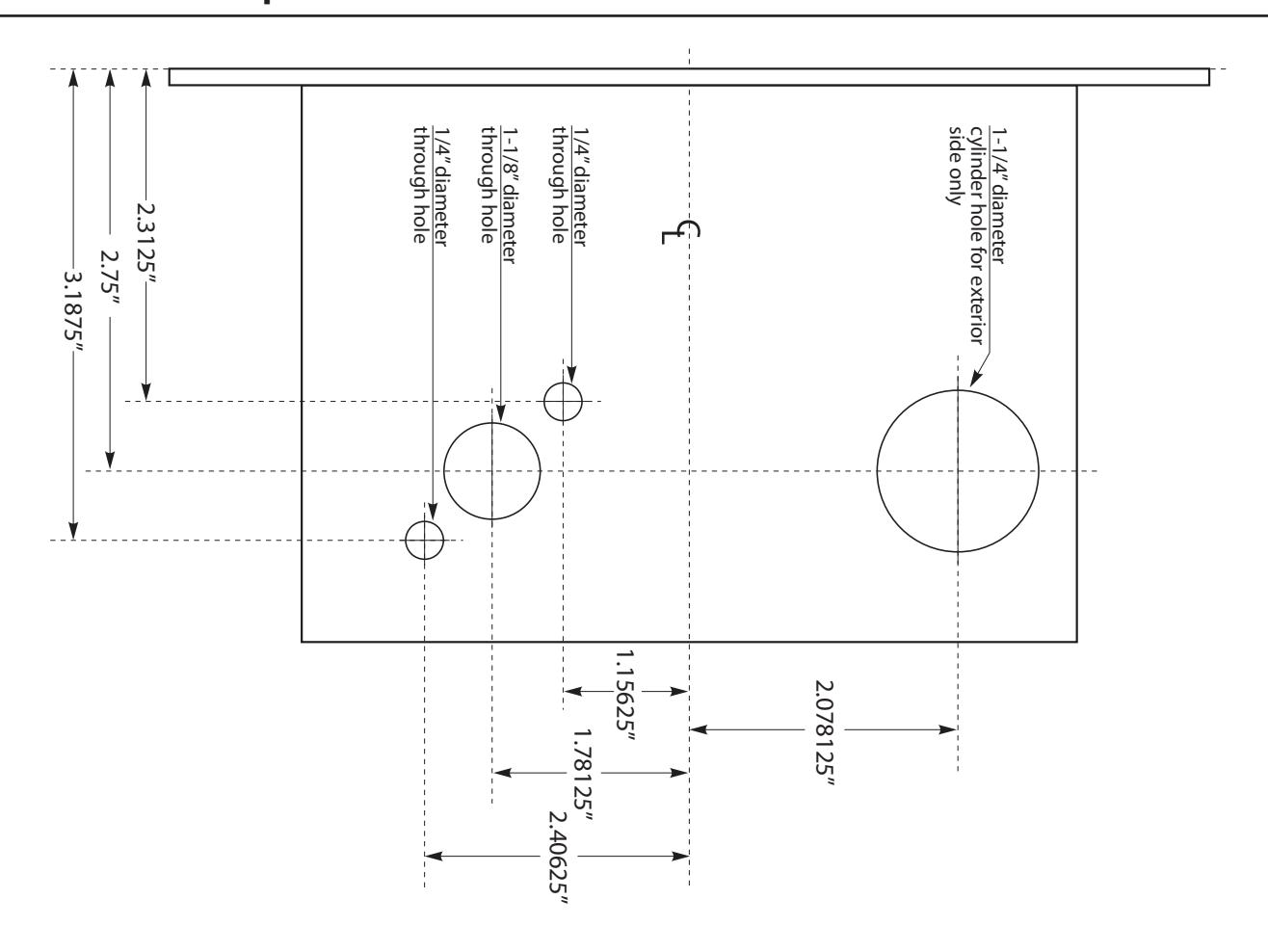
Template for ML370/371/372/373/336/337 Mortise Locks