Locknetics PPH 200 LED Push Plate Exit Button Installation Instructions 112111
Open the original PDF document
View PDFPPH-200-LED Push Plate Exit Buttons Installation Instructions
General Descriptions
Locknetic's NEW line of LED illuminated push plate exit buttons are designed to provide maximum visibility.
Features
- Stainless and impact resistant illuminated surface mount box
- Super-bright, high efficiency LED technology
LED Red/Blue illuminations to show door locked/unlocked status
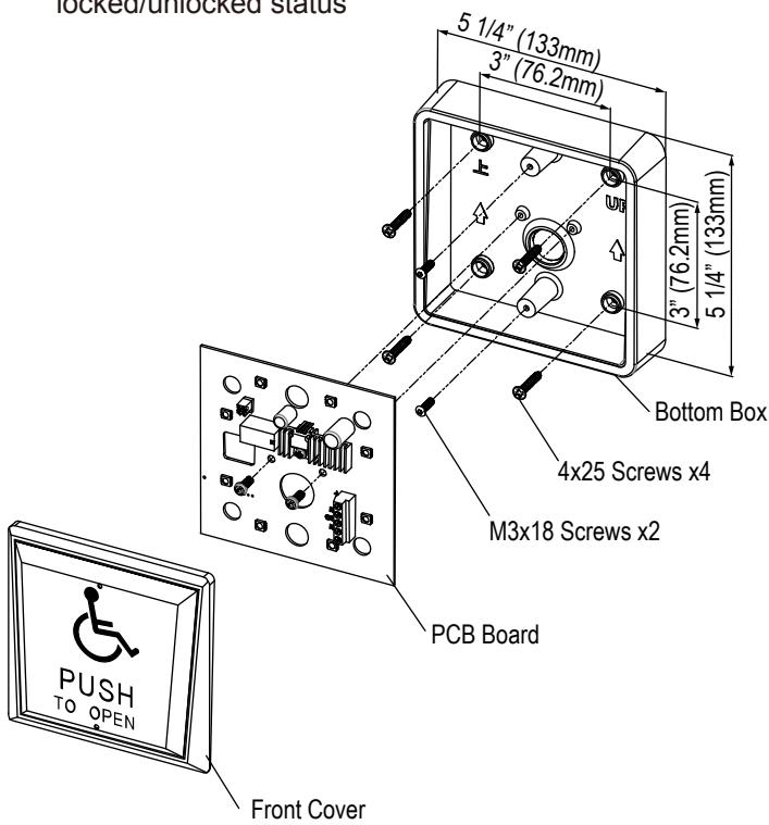
Installation Steps
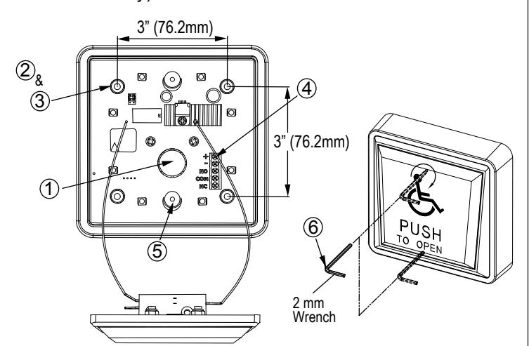
- ① Determine the wire access location and drill hole of sufficient size, or use center knock-out plug.
- ② Drill four required mounting holes 1/8" (3.2mm) minimum. Four indents are provided on 3" (76.2mm) centers for your convenience.
- ③ Pull wiring through access hole and mount the box to wall using four screws (4x25 screws).
- Remove circuit board from package and locate into the box with terminal strip at top. Wire as per Diagram (1) below.
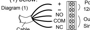
Power Input 12/24 VDC/AC
Output
/ Single pole double throw (SPDT)
- ⑤ Connect power and test for proper operation.
- © Screw in two provided M3x18 screws into the threaded center inserts, then attach wires to front cover. Install front cover over screws using the allen key provided. locate the screws and tighten (by hand only).
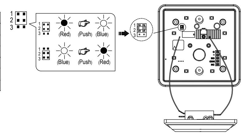
Setting LED Color Illuminations
| Position | Descriptions |
|---|---|
| 1 🔳 🔳 | When select JP1 & JP2, position, |
| 2 | Power in. Red LED is ON, |
| 3 🔳 | Push button to turn on Blue LED |
| 1 🔳 🔳 | When select JP2 & JP3, position, |
| 2 | Power in. Blue LED is ON |
| 3 | Push button to turn on Red LED. |
* Factory default setting as JP1 & JP2 position.
For details regarding the limited warranty:

1-877-671-7011
011 www.allegion.com/us

© Allegion 2017 47259496 Rev 08/17-a