Locknetics IPB300 IPB300N Series Push Button Installation Instructions 112101
Open the original PDF document
View PDFIPB-300 (Mushroom Style Button)
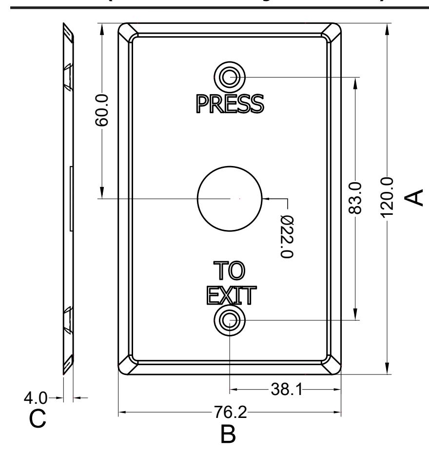
Length (A): 4 11/16" (120.0mm)
Width (B): 3" (76.2mm)
Depth (C): 5/32" (4.0mm)
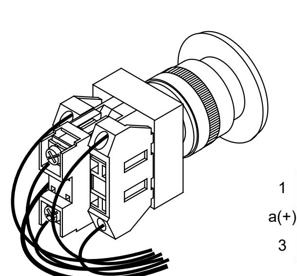
Push-button Wiring Diagram
- (1). Push-bu�on dry contacts ra�ngs: 6A/125VAC or 3A/300VAC. Do not exceed the above ra�ngs for safe opera�ons.
- (2). For Normally Open requirement, connect wires to A dry contacts of Push-bu�on.
- (3). For Normally Closed requirement, connect wires to B dry contacts of Push-bu�on.

- (4). Remove Push-bu�on from S/W assembly by unscrewing Red/Green cap.
- (5). Select desired color cap.
- and screw on desired color bu�on. (6). Place S/W assembly under faceplate
| Wire Color | |||
|---|---|---|---|
| (Blue) | 1 | 2 | (Blue) |
4 3 (Yellow) (Yellow)
12 VDC b a(+) L (Red) (Black)
Back view
2 b 4
a b Lamp
1 2 NO.
3 4 NC.
For details regarding the limited warranty:
Customer Service

Allegion 2018 47259494 Rev. 01/18-c 1-877-671-7011 www.allegion.com/us
IPB-300N (Mushroom Style Button-Narrow Stile)
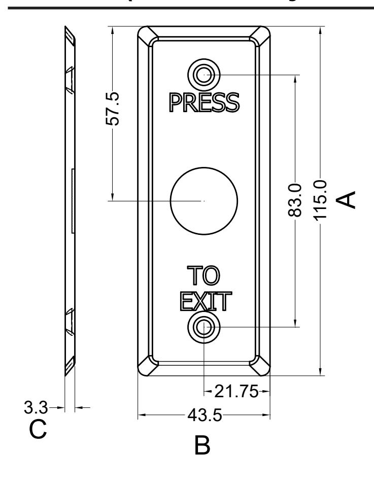
Length (A): 4 1/2" (115.0mm) Width (B): 1 3/4" (43.5mm) Depth (C): 1/8" (3.3mm)
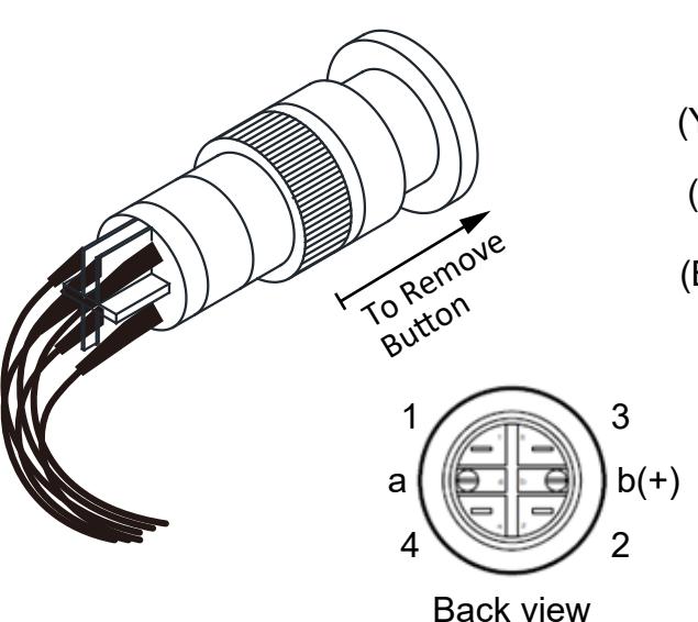
Push-button Wiring Diagram
- (1). Push-button dry contacts ratings: 5A/25VAC.Do not exceed the above ratings for Safe operations.
- (2). For Normally Open requirement, connect wires to 3 4 dry contacts of Push-button.
- (3). For Normally Closed requirement, connect wires to 1 2 dry contacts of Push-button.
To Assemble:
- (4). Remove Push-button cap (Red/Green) by pulling installed cap off.
- (5). Select desired Push-button color.
- (6). Press selected button onto S/W assembly with faceplate in between S/W and Push-button.
Wire Color
(Yellow) 1 Q 2 (Yellow)
(Blue) 3 0 0 4 (Blue)
(Black) a —(L)— b(+) (Red) 12 VDC
a b→ Lamp
1 2 → NC.
3 4 → NO.