Locknetics IPB100 IPB100 N Series Push Button Installation Instructions 112100
Open the original PDF document
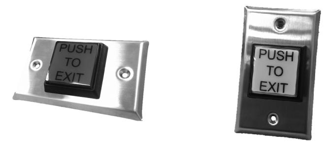
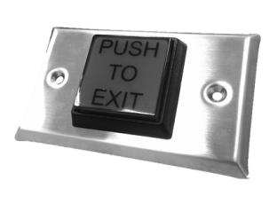
View PDFIPB Series Installation Instructions
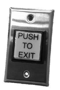
IPB-100, IPB-100-N
Specifications
| LED | |
|---|---|
| 12/24 VDC | |
| 24 VDC 10 ma | |
| SWITCH | |
|---|---|
| 3A @ 125VAC | |
| -30 to +50 Celsius | |
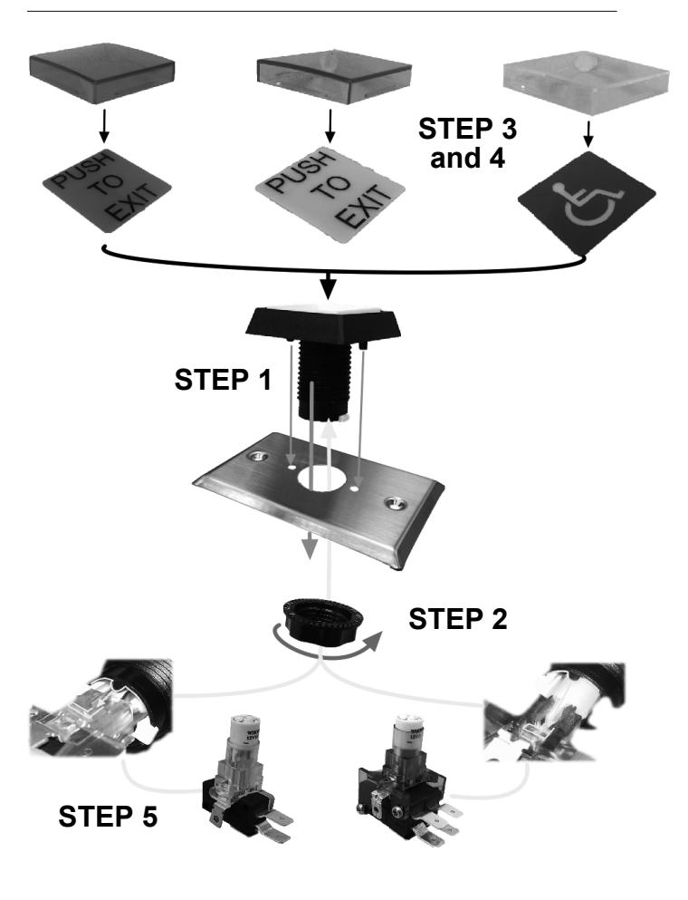
Installation
- (1) Insert the push button assembly into the faceplate
- (2) Lock the provided nut onto the push button assembly from the back side of the faceplate
- (3) Choose the preferred lens cap included in the box
- (4) Assemble chosen lens cap to the push button assembly
- (5) Twist the chosen lamp-holder / switch assembly (SPDT & DPDT Provided) into the push button
Technical & Warranty Information
Contact Allegion Customer Care at 877-671-7011
For details regarding the limited warranty:

1-877-671-7011 www.allegion.com/us

Instructions d'installation pour la série IPB
IPB-100, IPB-100-N
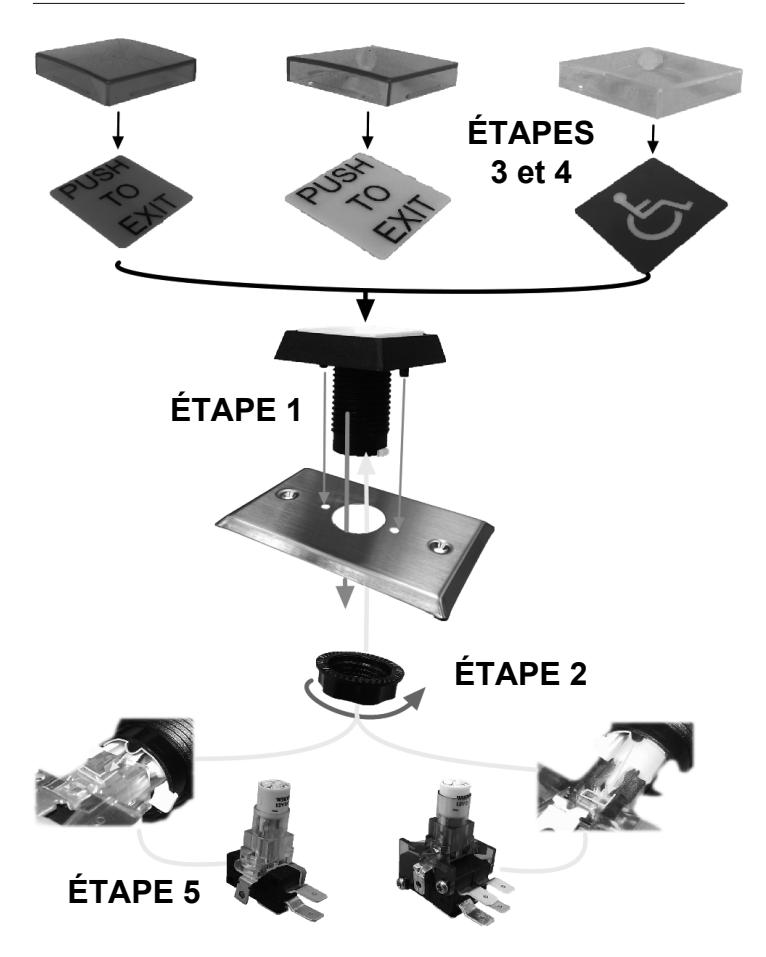
Vue éclatée de la série IPB
Spécifications
| Tension de fonctionnement | 12/24 V c.c. |
|---|---|
| Tolérance de tension | ±10 % |
| Appel de courant | 3 A à 125 V c.a. |
| Température de fonctionnement | -30 à +50 Celsius |
Installation
- (1) Insérer l'ensemble de bouton-poussoir dans la têtière.
- (2) Serrer le boulon fourni sur l'ensemble de bouton-poussoir depuis l'arrière de la têtière.
- (3) Choisir un capuchon parmi ceux inclus dans la boîte.
- (4) Fixer le capuchon choisi sur l'ensemble de bouton-poussoir.
- (5) Insérer la douille/l'interrupteur (unipolaire bidirectionnel et bipolaire bidirectionnel fournis) choisi dans le bouton-poussoir.
Renseignements techniques et relatifs à la garantie
Communiquez avec le service client d'Allegion au 877-671-7011
Pour plus de détails concernant la garantie limitée :
Service à la clientèle
1-877-671-7011 www.allegion.com/us