Locknetics EMS100 Exit Motion Sensor Installation Instructions 112099
Open the original PDF document
View PDFEMS-100 Series
Exit motion sensor Instruction

Product Description
The EMS-100 is designed for use on request-to-exit applications with maglocks and electric strikes. This sensor is not an automatic door activation sensor. It is a request to exit sensor used to release a lock.The unit is a passive infrared detector that uses digital signature analysis for activation. The EMS-100 is not recommended for activation on pedestrian automatic doors because the passive infrared technology recognizes temperature changes (i.e. body temperature) for detection. As such, the EMS-100 will not recognize motion associated with inanimate objects such as hospital beds, gurneys, shopping carts, etc.
The key advantages of the EMS-100 are fast detection, adjustable sensing fields, and no false detection from inanimate objects.
Component ID
SENSOR AND HOUSING
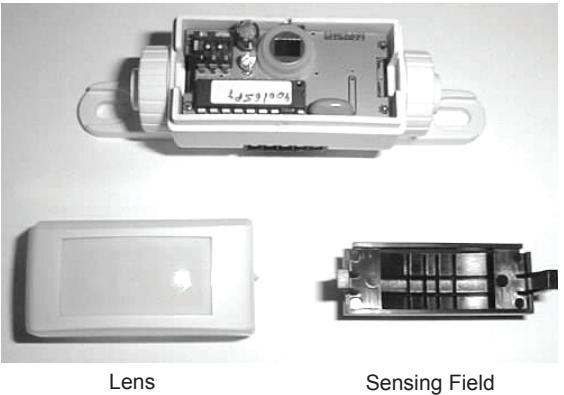
Adjustment Mask
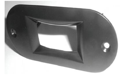
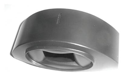
OPTIONAL ACCESSORIES:
Ceiling Adapter
Surface Adapter
Technical Specifications
| Description | Specification | |
|---|---|---|
| Technology | Passive infrared with microprocessor | |
| Mounting Height - Variable | 10'-0" max. (Recommended 6'-6" to 8'-0" ) | |
| Mounting Angles | 0 to 180° | |
| Power Supply | 12-24 VAC –10/+10% (50/60Hz) | |
| 12-24 VDC –10/+30% | ||
| Current Consumption | <10 mA (20mA if the relay output is activated) | |
| Contact Rating (Output Relay) | 1 A/ 75 VDC or 50 VAC Potential free contact NO/NC | |
| Optical Characteristics | Passive infrared with four elements | |
| 15 Fresnel lenses with full independent masking possibilities | ||
| Warm-up Time | 10 seconds | |
| Response Time | Max 200 microseconds | |
| Relay Hold Time | 0.5 or 2 seconds | |
| Operating Temperature | -22°F to +140°F (-30°C to +55°C) | |
| Immunity | Immune to electrical and radio frequency interference | |
| Cable | 9 feet of four-conductor cable with 5-pin connector | |
| Weight | 1.4 oz. (40g) | |
| Dimensions: | ||
| Sensor | 4"L (100 mm.) x 1"H (25 mm.) x 1.8"W (45 mm.) | |
| Housing Color | Black | |
For details regarding the limited warranty:
Customer Service
1-877-671-7011 www.allegion.com/us

Safety Precautions

- Shut off all power going to the header before attempting any wiring procedures.
- Maintain a clean & safe environment when working in public areas.
- Be constantly aware of pedestrian traffic around the door area.
- Always stop pedestrian traffic through the doorway when performing tests that may result in unexpected reactions by the door.
- Always check placement of all wiring before powering up to insure that moving door parts will not catch any wires and cause damage to equipment.
- Ensure compliance with all applicable safety standards (i.e. ANSI A156.10) upon completion of installation.
Installation Instructions
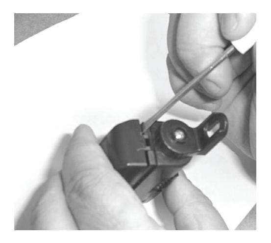
PREPARE THE SENSOR:
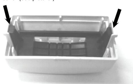
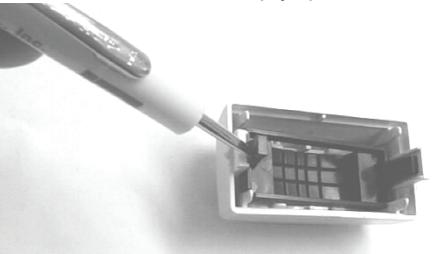
a. Open the cover . Insert a small screwdriver on the side of the housing (see picture) and gently pry the cover off.
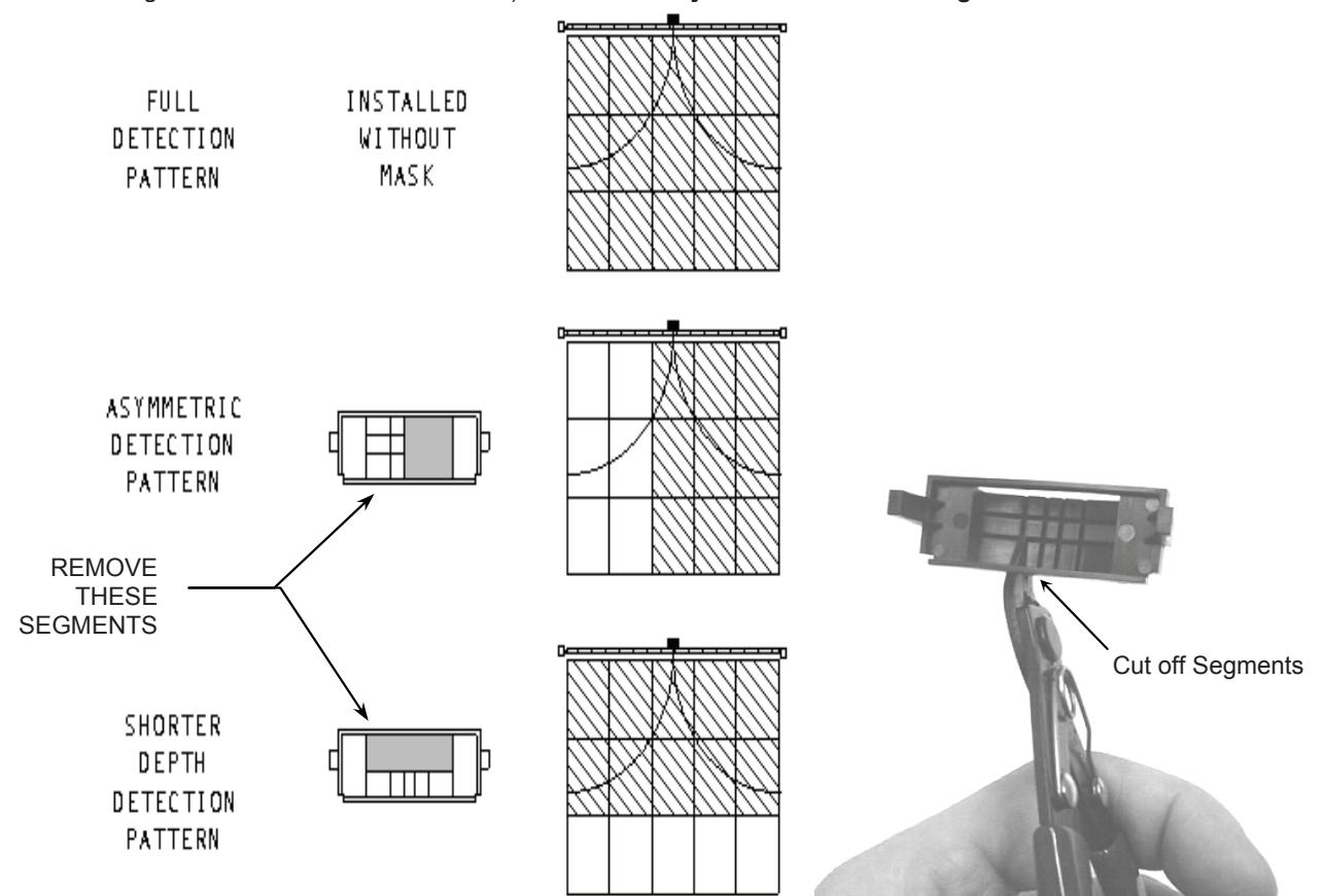
b. Adjust the sensing field to the specific application. To adjust the field, remove segments of the lens with a diagonal cutter or a similar tool. It is not necessary to use the masking lens (installing the sensor without the mask will give the maximum detection size.) It is necessary to cut at least one segment to allow detection.

Installation Instructions (cont.)
Reinstall the mask (if needed.) The mask can only by installed one way. Place the mask inside the cover so that the legs of the mask slide into the clips. Gently work the mask's legs into the cover until it clicks. Then the mask will be completely inside the cover (see picture.)
If the masking lens needs to be removed from the cover, pry up with a screwdriver on the small legs of the lens.
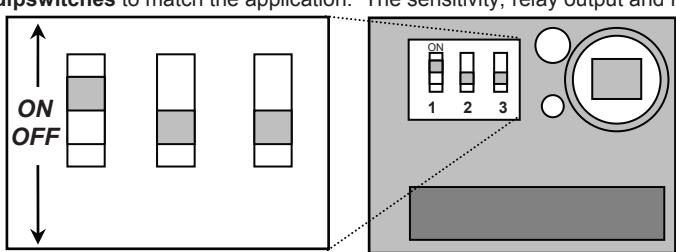
Adjust the dipswitches to match the application. The sensitivity, relay output and hold time can all be adjusted.
|
DIP
SWITCH |
SETTING | ADJUSTMENTS |
FACTORY
SETTING |
|---|---|---|---|
| 1 | SENSITIVITY |
ON: HIGH
OFF: LOW |
HIGH |
| 2 | RELAY OUTPUT | ON: PASSIVE OUTPUT* OFF: ACTIVE OUTPUT** | ACTIVE |
| 3 |
HOLD TIME
(FLY) |
ON: 2 sec
OFF: 0.5 sec |
2 sec |
|
HOLD TIME
(FLY ERT) |
ON: 30 sec
OFF: 15 sec |
15 sec |
- Passive output: relay contact open during detection and closed during non-detection.
- Active output: relay contact closed during detection and open during non-detection.
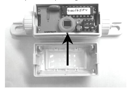
- Replace the cover. The cover is keyed and may only be installed one way. Match the small tab in the center of the cover to the slot in the housing (see arrow). Gently push the cover on until it snaps. It is easiest to insert both legs of the cover at once and then push the two pieces together.

Mechanical Installation
MOUNTING THE EMS-100
- The sensor must be firmly fastened in order to avoid any vibrations.
- b. Make sure there are no objects in the sensing field that could move.
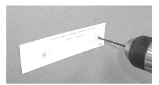
- attach the template to the frame above the door. brill and pass the cable through the template.
- e. Place the sensor on the template and attach with the two screws provided.
© Electrical Installation & Power On
WIRING THE SENSOR
Connect the cable of the sensor to the unit as shown below. The connector is removable for ease of wiring. Note: The input power is not polarity sensitive.
| PIN | FUNCTION |
|---|---|
| 1 | 12-24 V (POWER) |
| 2 | 12-24 V (POWER) |
| 3 | RELAY COM |
| 4 | RELAY NO |
| 5 | RELAY NC |
USING THE SENSOR
LED SIGNAL - The LED will flash for a few seconds when the unit is started up. The LED will also light up when the sensor detects motion.
Troubleshooting
| SYMPTOM | PROBABLE CAUSE | CORRECTIVE ACTION |
|---|---|---|
| The door will not unlock The LED does not light up | The sensor power is off |
|
| Detection occurs and the LED lights, but lock does not release. |
The relay output is not correct
The wiring is not correct |
|
| The size of the sensing field does not meet requirements | The cut out of the masking lens is not correct | Cut a new lens to meet the required sensing field size |