LockeyUSA Websafe EC Series Installation Electronic Lock Instructions
Open the original PDF document
View PDFPlease check that template is correct size before use – copies can be distorted
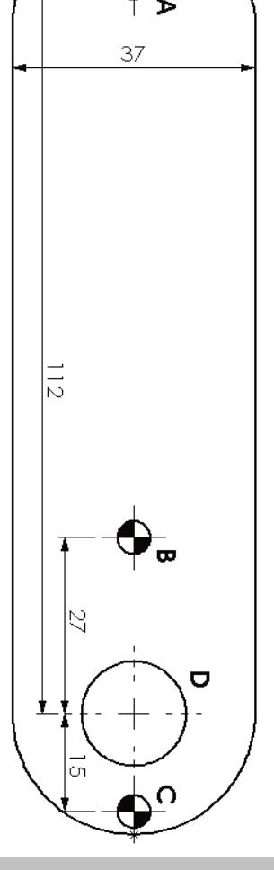
Installation Template
HOLES A, B & C DIAMETER 4.5 / 5.0mm HOLE D DIAMETER 16.0 / 16.5mm ALWAYS USE HOLE A
IMPORTANT NOTE:
Before drilling holes, please ensure that the position of the lock will allow clearance for the cam to function.

EC-Series Digital Combination Lock INSTALLATION INSTRUCTIONS
IMPORTANT NOTE:
Before drilling holes, please ensure that the position of the lock when fitted will allow clearance for the cam to function.
USE EITHER OR BOTH OF HOLES B & C www.LockeyLocks.com
The EC Series locks can be mounted on cupboards, cabinets, lockers, etc. as a direct replacement for existing cam locks. It can also be easily installed on cupboards and cabinets that do not have an existing locking device.
Special Notes:
- Before installing the EC Series Lock, insert 2 Alkaline AA batteries and familiarize yourself with the operation and programming.
- Unless manufactured to special order, the lock is supplied in the "PRIVATE" operating mode. In this mode, the user must enter a four-digit User Code to open it. The unit will re-lock itself after four seconds. The lock can be opened at any time using the Master Code.
- Your lock is not secure until you have changed the default Master Code and User Code.
- Keep track of your master code as it is NOT possible to make any programming changes without it. Please see programming guide to set your own codes
IMPORTANT NOTES
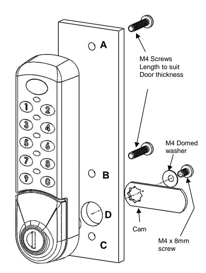
The lock can be mounted using two or three screws. Always use the screw position "A" behind the logo button. Use either of the other two positions "B" or "C" or both if preferred. Before drilling holes, please ensure that the position of the lock when mounted will allow clearance for selected cam to work.
ENSURE BATTERIES ARE CORRECTLY INSERTED BEFORE MOUNTING LOCK
Installation Guide:
A) New Installation
- Step 1 Place template on door and mark TWO 4.5mm (3/16") holes (refer to installation diagrams). Use hole position "A" and either of positions "B" & "C". Mark ONE 16mm (5⁄8") hole (position "D").
- Step 2 Drill both holes and the 16mm clearance hole.
- Step 3 Mount the Digital Combination Lock to the door by passing the barrel through the 16mm (5⁄8") hole.
- Step 4 Secure with at least two screws to suit your door thickness.
- Step 5 Tighten the upper and lower screws.
- Step 6 Select the cam which suits your door and frame and attach it to the square shaft at the end of the barrel using a M4 x 8 screw and domed spring washer.
- Step 7 Test the operation of the lock using the factory User Code.
- Step 8 If the lock is functioning correctly, CHANGE THE DEFAULT MASTER CODE and DEFAULT USER CODE and program the lock using the programming and operating instructions enclosed. Write down the new Master Code and User Code and be sure not to lose it. It is not possible to program the lock without it.
- B) Replacing existing cam lock with the Digital Combination Lock
- Step 1 Remove existing cam lock.
- Step 2 Place installation template on door over hole left by cam lock (position "D") and mark TWO 4.5mm (3/16") holes (refer to installation diagrams). Use hole position "A" and either of positions "B" & "C".
- Step 3 Drill the two 4.5mm (3/16") mounting holes.
- Step 4 Continue installation from step 3 to 8, above.
HOLES A, B & C DIAMETER 4.5 / 5.0mm HOLE D DIAMETER 16.0 / 16.5mm ALWAYS USE HOLE A USE EITHER OR BOTH OF HOLES B & C