LockeyUSA TB250 450 650 Gate Hardware Instructions Updated 2.15.16 Compressed 4
Open the original PDF document
View PDF

ADJUSTABLE HYDRAULIC GATE CLOSER TB250, TB450, TB650 INSTALLATION INSTRUCTIONS
Important:
-
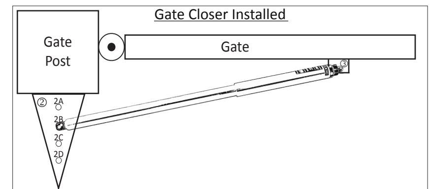
This gate closer is mounted on the swing/open side of the gate and pushes the gate closed.
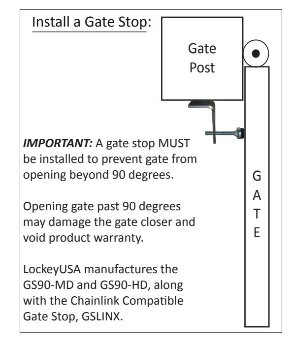
- A Gate Stop must be installed to keep gate from opening beyond 90 degrees.
- If using tension/spring hinges, release all tension and remove spring closers.
- Do NOT use with bulldog/strap style hinges. For best results, use male/female style hinges.
| No. | Part Name | Qty. |
|---|---|---|
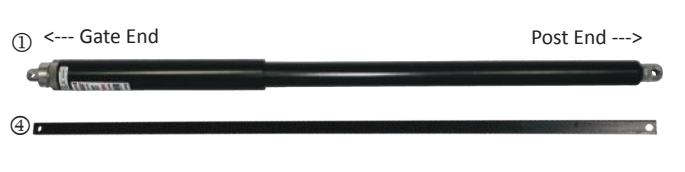
| 1 | Hydraulic Cylinder | 1 |
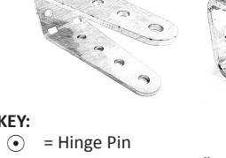
| 2 | Post Bracket (Triangular) | 1 |
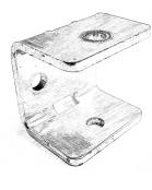
| 3 | Gate Bracket | 1 |
| 4 | Fitting Bar | 1 |
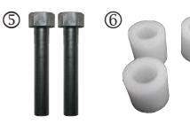
| 5 | Securing Pins (Hexagon Head) | 2 |
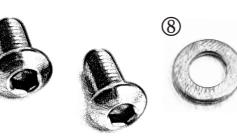
| 6 | Spacers | 4 |
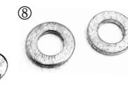
| 7 | Cap Screws | 2 |
| 8 | Washers | 2 |
| Gate Closer | 36" Gate | 48" Gate | 60" Gate | ||
|---|---|---|---|---|---|
| Added Opening Force | |||||
| No Closer | 3/4 lb. | 1/2 lb. | 1/4 lb. | ||
| TB250 | 6 lbs. | 4 lbs. | 3 lbs. | ||
| TB450 | 10 lbs. | 8 lbs. | 6 lbs. | ||
| TB650 | 13 lbs. | 10 lbs. | 8 lbs. | ||
| Added Force at 45 degrees Open | |||||
| TB250 | 7 lbs. | 5 lbs. | 4.5 lbs. | ||
| TB450 | 13 lbs. | 9.5 lbs. | 8 lbs. | ||
| TB650 | 18.5 lbs. | 13.5 lbs. | 12 lbs. | ||
|
Constant
Closing Pressure |
Approximate
Width |
Approximate
Weight |
|
|---|---|---|---|
| 0 lbs. | |||
| 45 lbs. | 36-52 Inches | 50-125 lbs. | |
| 90 lbs. | 40-64 Inches | 75-175 lbs. | |
| 135 lbs. | 44-72 Inches | 150-250 lbs. | |
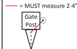
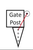
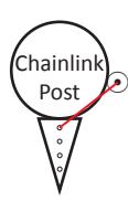
• = Hinge Pin = MUST measure 2-4"
INSTALLATION INSTRUCTIONS:
Step 1: Secure Post Bracket (#2) to Gate Post *This step is the MOST important. The Post Bracket (#2) MUST be mounted first.* Hold Post Bracket (#2) to the face of the gate post.
Measure from the center of the first hole on Post Bracket (#2A) to the center of the Hinge Pin⊙.
This measurement MUST be between 2" and 4".
Clamp bracket into place.
Note: Regardless of hinge arrangement, the measurement from the center of the Hinge Pin € to the center of hole 2A on Post Bracket (#2) must not exceed 4" or damage to the gate closer may occur.

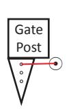

Step 2: Measure/Secure Gate Bracket (#3)
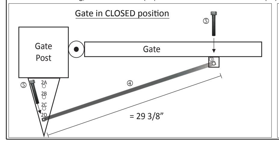
With gate in closed position, attach Fitting Bar (#4) to Post Bracket (#2) using a Securing Pin (#5) in hole 2-D (shown below (left)).
Next, place a Securing Pin (#5) in the opposite end of the Fitting Bar (#4) and secure to the Gate Bracket (#3).
Hold Gate Bracket (#3) to the gate and clamp into place.
The distance from the center of hole 2-D and the center of the Gate Bracket must measure 29 3/8".
Clamp/secure brackets then remove Fitting Bar (#4).
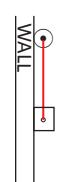
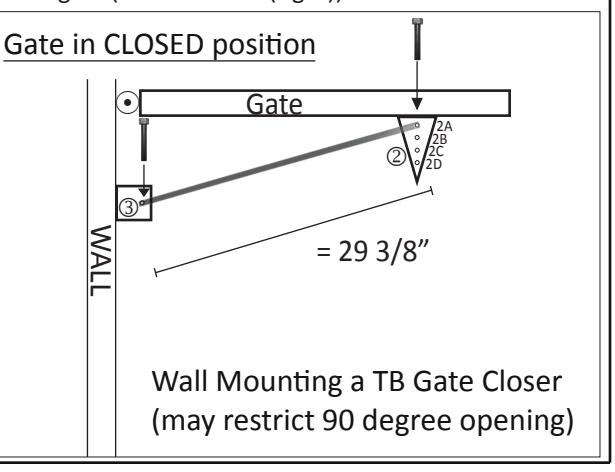
Note: If wall mounting, use Gate Bracket (#3) on the wall and the Post Bracket (#2) on the gate (shown below (right)).
INSTALLATION INSTRUCTIONS CONTINUED:
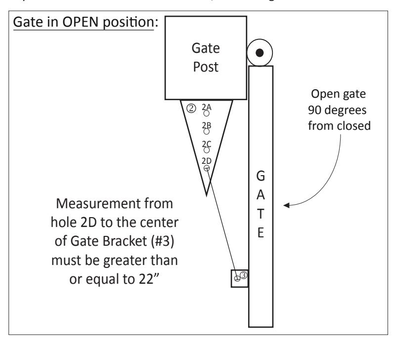
Step 3: Verify Measurements in OPEN Position
Open gate 90 degrees from closed position.
Measure the distance from the center of hole 2D on the Post Bracket (#2) to the center of the Gate Bracket (#3).
The distance MUST measure 22" or MORE. If the distance is less than 22", start back at Step 1.
Once you have verified all measurements, close the gate and secure all mounting brackets.
Step 4: Install your LockeyUSA TB Gate Closer
Grease Securing Pins (#5) with light silicone grease.
Before installing, make sure gate closer is compressed under 29" end to end.
Place "Post End" of your gate closer to Post Bracket (#2).
Secure using a greased Securing Pin (#5) and two Spacers (#6), one spacer on top and one on bottom of the closer. Secure with a Washer (#8) and Cap Screw (#7) and tighten (shown to the right).
Next, open the gate slightly to align the hole on the "Gate End" of the gate closer to Gate Bracket (#3).
Secure using a greased Securing Pin (#5) and two Spacers (#6), followed by a Washer (#8) and Cap Screw (#7). Tighten.
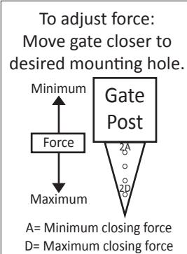
Adjusting your LockeyUSA TB Gate Closer
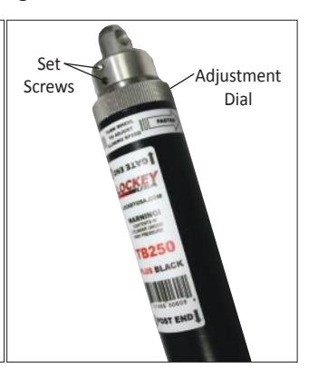
With the gate closer secured to the gate, slowly turn the adjustment dial towards FASTER. The gate will slowly close.
Open the gate and let it close again, using the dial to adjust gate closing speed.
When the desired closing speed is met, tighten set screws on the adjustment dial to prevent speed tampering.

Visit www.LockeyUSA.com for more gate security products.