LockeyUSA Standard 3 in 1 Panic Hardware Shield instructions
Open the original PDF document
View PDF

PANIC SHIELD KIT INSTALLATION INSTRUCTIONS
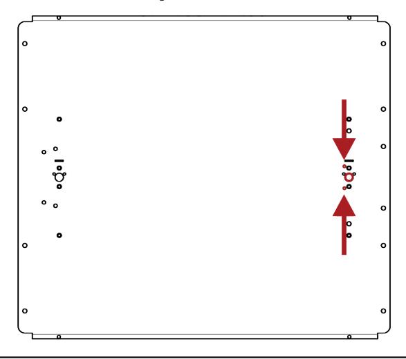
Step 1: Determine the hole pattern that matches the panic bar you will be installing on the panic shield & situate the panic shield appropriately.
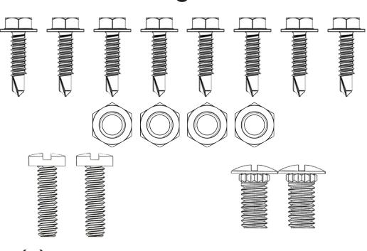
PB1100/PB1142 Panic Bar Hole Pattern & Fastening Materials
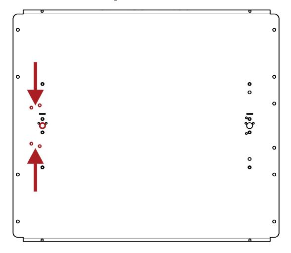
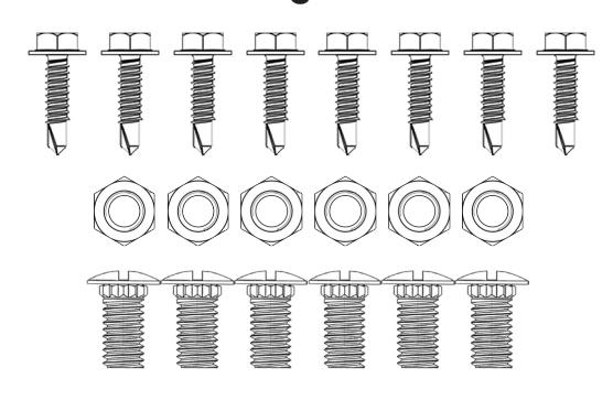
- (8) 1" Stainless Self Drilling Screw
- (6) ¼" Nylon Insert Lock Nut
- (6) ¼" x 9/16" Ribbed Track Bolt
DETEX V40 Series Panic Bar Hole Pattern & Fastening Materials
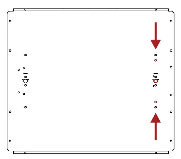
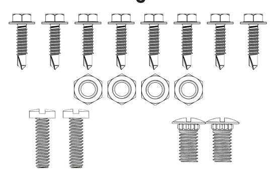
- (8) 1" Stainless Self Drilling Screw
- (4) ¼" Nylon Insert Lock Nut
- (2) ¼" x 1" Pan Phillips Machine Screw
- (2) ¼" x 9/16" Ribbed Track Bolt
PB2500/PB2542 Panic Bar Hole Pattern & Fastening Materials
- (8) 1" Stainless Self Drilling Screw
- (4) ¼" Nylon Insert Lock Nut
- (2) ¼" x 1" Pan Phillips Machine Screw
- (2) ¼" x 9/16" Ribbed Track Bolt

PANIC SHIELD KIT INSTALLATION INSTRUCTIONS
Step 2: Determine adjusted size of panic shield
All Panic Shields have (1)inside and (1)outside adjustable sliding panel & are designed to be mounted on the inside of the gate. For chain-link gates, leave a space of approximately 1" on each end for the latch and hinges. Panic Shields can be mounted on the left or right side of gates 28"-54" wide (extension plates are available, sold separately). Determine the size of the mounting plate needed for proper installation and make note of expanded panel size. The inside panel is predrilled to fit LockeyUSA PB1100/PB1142, LockeyUSA PB2500/PB2542, or any Detex V40 Series Panic Bar.
Mounting Tip: Determine gate side. If using a lock box, install prior to mounting the panic shield on the gate.
Step 3: Install lock box
Install a keyed cylinder or keyless panic trim at this time. In most cases the lock box is held on with the mounting screws from the locking mechanism. If using boxes other than the PSGB5 (keyed cylinder) or the PSGB200 (285-P Keyless Panic Trim), you WILL need to drill mounting holes accordingly (mounting screws are supplied with lock). After the lock box is installed, place the tail piece in the proper position.
You are now ready to install your panic exit device. Step 4: Fitting the panic bar to the panic shield
PB1100/PB1142: See Panic Bar Installation Instructions and mount the panic bar using the (4) ¼" x 9/16" Ribbed Track Bolts and (4) ¼" Nylon Insert Lock Nuts included with the panic shield. Make sure the tail piece is centered and is in the proper position. The tail piece MUST be in the proper position to work correctly. Next, adjust the panic shield to the size determined in Step 2. If the panic bar is too long for the panic shield, cut the panic bar down to the size needed for proper installation. After the panic bar and shield are sized correctly, to install the panic bar end cap, drill (2) holes measuring ¼" and bolt it into place with the (2) ¼" x 9/16" Ribbed Track Bolts and (2) ¼" Nylon Insert Lock Nuts.
PB2500/PB2542: See Panic Bar Installation Instructions and mount the panic bar using the (2) ¼" x 1" Pan Phillips Machine Screws and (2) ¼" Nylon Insert Lock Nuts included with the panic shield. Make sure the tail piece is centered and is in the proper position. The tail piece MUST be in the proper position to work correctly. Next, adjust the panic shield to the size determined in Step 2. If the panic bar is too long for the panic shield, cut the panic bar down to the size needed for proper installation. After the panic bar and shield are sized correctly, to install the panic bar end cap, drill (2) holes measuring ¼" and bolt it into place with the (2) ¼" x 9/16" Ribbed Track Bolts and (2) ¼" Nylon Insert Lock Nuts.
pg 2 DETEX V40: See Panic Bar Installation Instructions and mount the panic bar using the (2) ¼" x 9/16" Ribbed Track Bolts and (2) ¼" Nylon Insert Lock Nuts included with the panic shield. Make sure the tail piece is centered and is in the proper position. The tail piece MUST be in the proper position to work correctly. Next, adjust the panic shield to the size determined in Step 2. If the panic bar is too long for the panic shield, cut the panic bar down to the size needed for proper installation. After the panic bar and shield are sized correctly, to install the panic bar end cap, drill (2) holes measuring ¼" and bolt it into place with the (2) ¼" x 1" Pan Phillips Machine Screws and (2) ¼" Nylon Insert Lock Nuts.

PANIC SHIELD KIT INSTALLATION INSTRUCTIONS
Step 5: Install Panic Bar/Shield on the gate
Your panic bar should be mounted to the panic shield at this time. Check to be sure the lock mechanism works properly. If working properly, you are ready to install the panic shield and bar to the gate.
Measure 40" up from the ground/surface and mark on the gate. Your panic bar must be 40" from surface (40 – 42 inches is the standard height to mount exit devices). Check your local code for proper height. Place the panic shield on the inside of gate. Attach the panic shield to the gate using the supplied (8) 1" Stainless Steel Self-Drilling Screws. It is helpful to pre-drill pilot holes.
Your panic shield is now installed.
Next, install the panic bar strike/keeper. If using a gate stop/strike bracket, install it at this time. We recommend using a LockeyUSA PSSB Panic Stop/Strike Bracket with LockeyUSA Panic Shields.

888.395.0163 www.LockeyUSA.com