LockeyUSA Slim Line 910 Electronic Lock Instructions
Open the original PDF document
View PDFPD2 PD2 PD2 PD2
Keypad Electronic Deadbolt Installation Instructions
SPECIFICATIONS
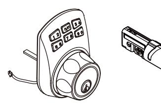
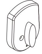
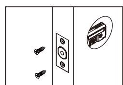
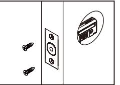
Exterior Assembly
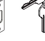
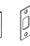
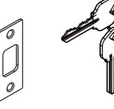
Latch Strike Keys

Mounting Plate Interior Assembly
Mounting Screws Specifications
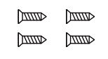
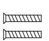
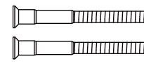
Wood screws Qty. 4
Machine screws Qty. 2
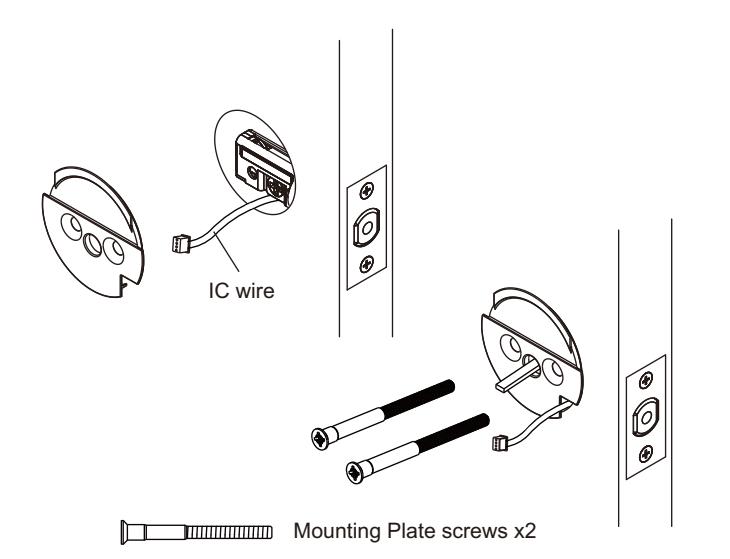
Mounting Plate screws Qty. 2
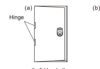
IDENTIFY DOOR HANDING
Face the door from the outside, the door is left-handed if the hinges are on the left side of the door, whereas the door is right-handed if the hinges are on the right side of the door.
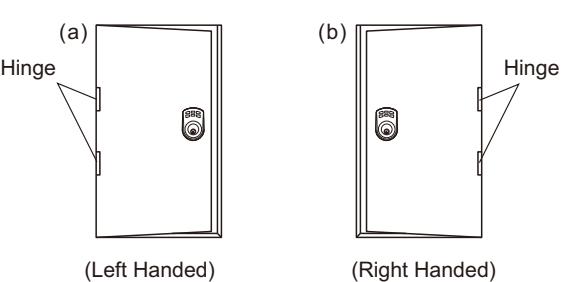
Note : When installing make sure the door opening side.

Left handed door install the spindle (vertically)


Right handed install the spindle (horizontally) door
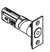
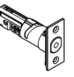
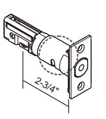
BACKSET DETERMINATION
Backset is a distance from door edge to center of hole on door face. Adjustable latch fits both backset of 2-3/8" (60 mm) and 2-3/4" (70 mm).
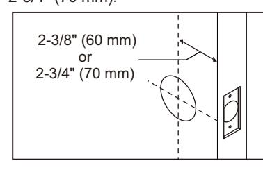
Remarks : The latch will adjust from 2-3/8" to 2-3/4" . Please adjust to fit your door. (60 mm) (70 mm)
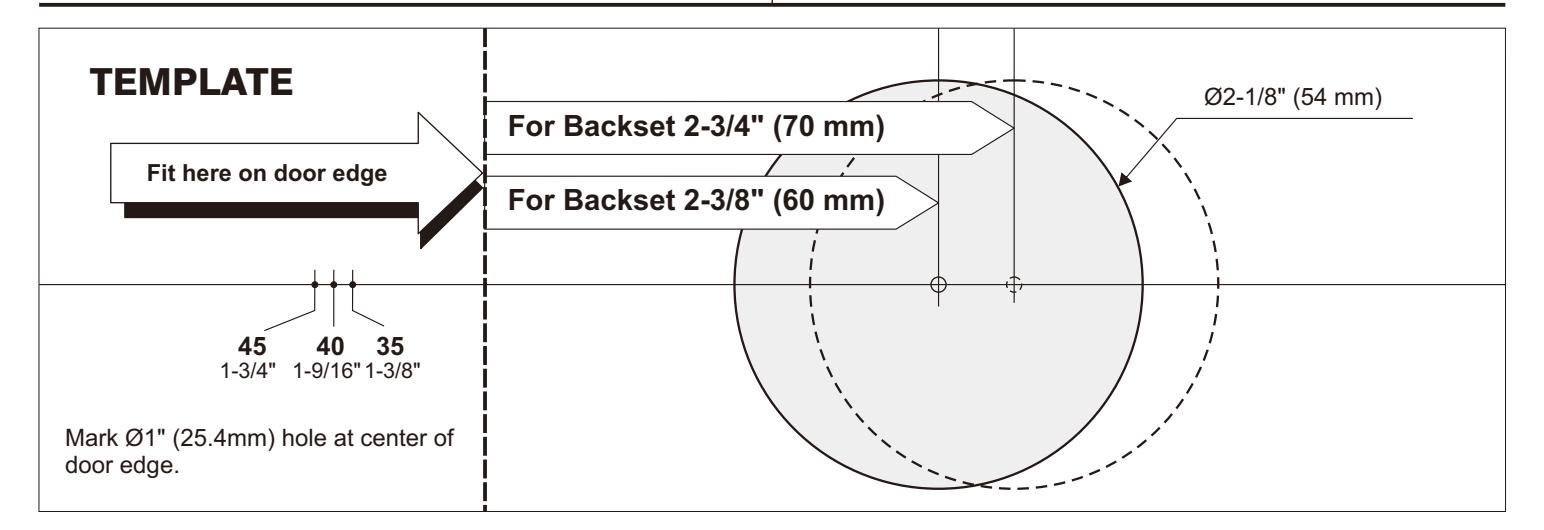
1. MARK THE DOOR WITH TEMPLATE
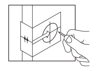
Select the height and backset as desired on the door face ; use the TEMPLATE as an indication to mark the center of the circle on the door face and the center of the door edge.
2. DRILL HOLES
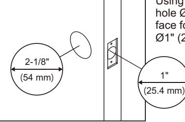
Using the marks as a guide to drill a hole Ø2-1/8" (54mm) through the door face for the lockset, then a hole of Ø1" (25.4mm) for latch.
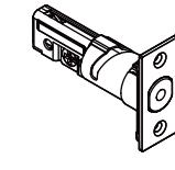
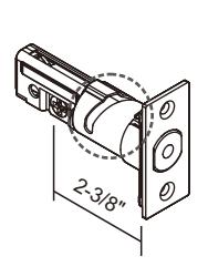
3. INSTALL LATCH
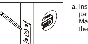
a. Insert the latch and ensure it is paralleled to the door face. Mark the outline of the faceplate, then take out the latch.
b. Chisel ( ) deep along the outline to allow the faceplate to be aligned with the door edge. 1/8" 3mm
c. Insert the latch and tighten it with screws.
Wood screws x 2
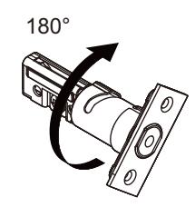
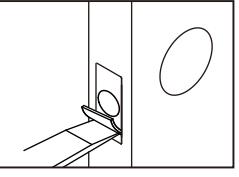
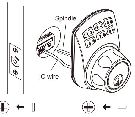
- a. Make sure the latch bolt is at unlocked position.
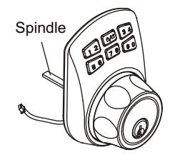
- b. Make sure you install the spindle inside the lock body correctly. If your door is LEFT-HANDED the spindle
should be VERTICAL in the latch. If your door is RIGHT-HANDED the
c. IC wire goes through the bottom of latch hole. spindle should be HORIZONTAL in the latch.
Left handed door install the spindle (vertically)
Right handed the spindle (horizontally) door install
5. INSTALL THE MOUNTING PLATE
Before securing the mounting plate to the deadbolt with the mounting screws make sure the IC wire fits cleanly through the corner of the plate.
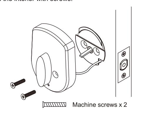
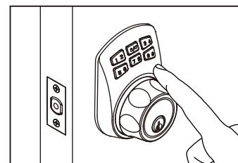
4. INSTALL THE EXTERIOR ASSEMBLY 6. INSTALL THE INTERIOR ASSEMBLY
Insert 3 AAA alkaline batteries into the battery case. Pull the IC cable from the side of the fixation plate and connect to the slot on the interior assembly.
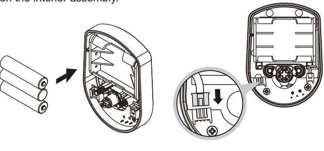
Match the interior assembly, the turnpiece should be vertical, and fasten the interior with screws.
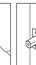
7. INSTALL STRIKE
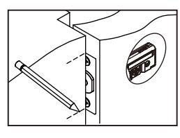
- a. To identify the center of strike : close the door, on the basis of the faceplate mark horizontal center line of strike. Ensure the center of faceplate and the center of strike are aligned. Use the mark as a guide outlines the strike.
-
- b. Chisel 5/64" (2mm) deep along the strike outline to allow the strike to be aligned with the doorframe.
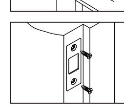
c. Insert the strike and tighten it with screws.
INSTRUCTIONS
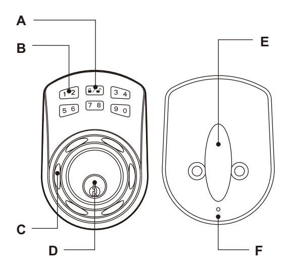
Programming Button A
Function setup & Lock and unlock.
Number Buttons B
Input the pass codes, each pass code is 4-10 digits in length.
Cylinder Housing C
Lock/unlock by control from cylinder housing.
Cylinder D
Retract / Extend the latch bolt by key from exterior.
Turn-Piece E
Retract / Extend the latch bolt from interior.
R Button (Reset) F
Restore default setting.
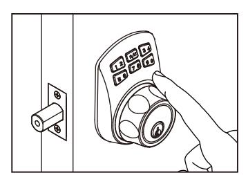
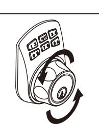
Unlock
To unlock the deadbolt - After you enter the user code (1,2,3,4) you must push the Lock & Unlock button. Now you have 5 seconds to manually turn the cylinder housing wheel.
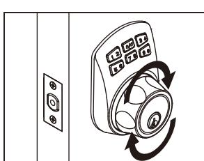
Lock
To lock your deadbolt - simply push the (A) Lock & Unlock button. Now you have 5 seconds to rotate the cylinder housing wheel.
REMARK
- 1. We recommend to use alkaline battery in order to stabilize the power supply.
- 2. Do not mix alkaline battery with regular zinc-carbon ones or mixed brands.
- 3. Do not use any chemical liquid or lubricating oil with additives to clean the lock body, it will damage the surface or even mainboard.
TROUBLESHOOTING
In installed, the cylinder housing don't rotated after press Programming Button
Note : In installing, spindle install mistake. Troubleshooting : Refer Identify door handing.
Battery life short
Note : Alkaline batteries better more than normal batteries.
Troubleshooting : Use alkaline batteries.
The lock don't setting user code
Note : Setting in lock state.
Troubleshooting : Confirm the latch is unlock state.
SETTINGS
| Programming Code (PC) : 0000 User Code (UC) : 1234 | ||
|---|---|---|
| Your new programming codes (PC) | Your new User Code (UC) | |
Note:Up to 20 sets of User Codes can be saved. User Codes should be 4-10 digits in length.
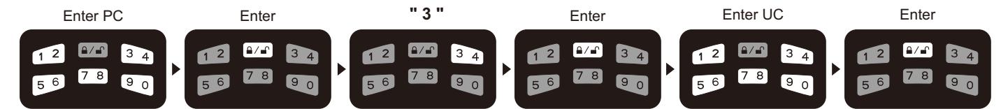
■ Delete individual User Code (UC)
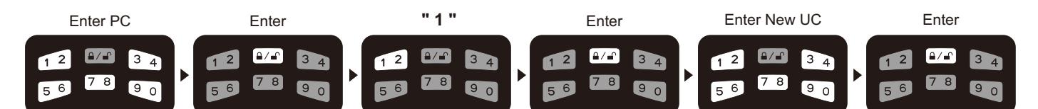
■ Create new User Code (UC)
■ Delete all User Codes (UC) at once
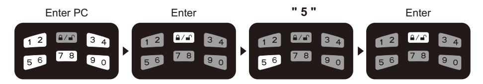
Note Auto-Locking and Keypad locking functions will be invalid when User Codes are deleted. The lock can only be operated by key during that time. :
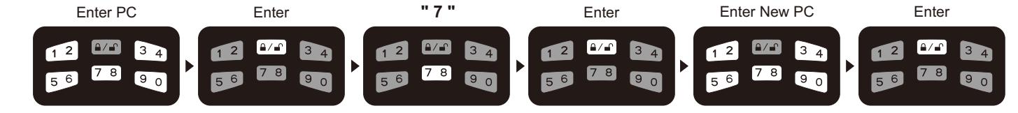
■ Change Programming Code (PC)
■ Restore Default Settings
Note : insert a pin into the hole under the bottom opening for 5 seconds. Three long beeps will indicate the restoration is completed.
OPERATION INDICATOR SOUNDS AND LIGHTS
| Lights | Sounds | Meaning | Troubleshoting |
|---|---|---|---|
| Flashes Green Once | 1 Beep | Successful Operation | |
| Flashes Red 3 Times | 3 Beeps | Operation Error | Repeat Operating |
| Flashes Red 5 Times | 5 Beeps | Code Input Error; System Shuts Down |
Waiting for 45 seconds
Repeat Operating |
| Flashes Red 10 Times | 10 Rapid Beeps | Low Battery Power | Chang the Battery |
| Flashes Green Twice | 2 Beeps | Successful Programming | |
| Flashes Orange 3 Times | 3 Long Beeps | Default Setting Restored | Repeat Setting |
| Flashes Orange Slowly | In Programming Mode |