LockeyUSA PB2500 and PB2500 Alarm Panic Hardware Instructions and Template
Open the original PDF document
View PDFLockey USA PB2500 Installation Instructions
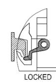
PATENTED LATCH AND STRIKE
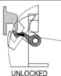
The device will only lock when the strike enters into the latch and depresses the silver colored Latch Guard. Depressing the Push Bar will not move or rotate the latch.
STEP 1: PREP DOOR
Tools needed:
#2 Phillips Screwdriver #16, 1/4", 3/8" Drill Bits Hammer 1-1/4", 5/8" Drill Bits (Trim) Center Punch I evel
Tape Pencil
Drill Hack Saw (for field cutting)
- 1. For devices installed with LTD or 08L Series Trim, use the trim template.
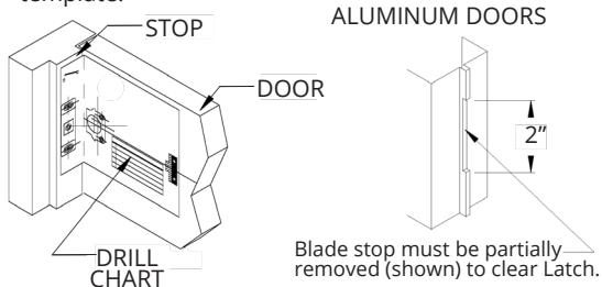
- 2. Fold template at perforation and place at the meeting edge of stop and door face.
- 3. Tape mounting template to door at a suggested height of 40-5/16" from finish floor level.
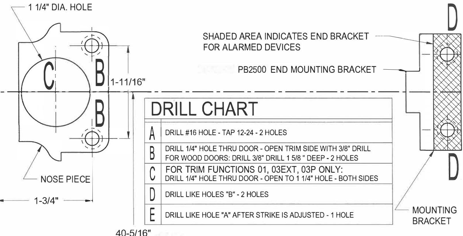
- 4. Drill door and frame mounting holes per drill chart on template.
FIT DEVICE TO DOOR
Door widths other than 36" or 48", use the formula: Distance between stops less 1-7/16" = Housing length
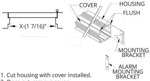
- 2. Once cut, remove cover.
- 3. Slide mounting bracket into track of housing.
Use mounting bracket as a guide to drill mounting holes.
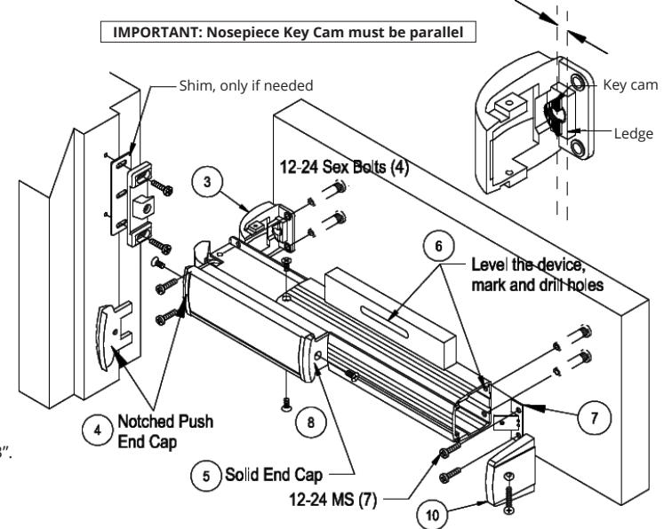
STEP 2: MOUNT DEVICE AND STRIKE
- 1. Use Mounting Template. Drill holes A and B. Drill hole C if using Outside Trim.
- 2. Remove Device from box and slide push bar/ chassis assembly beyond notched housing exposing mounting holes. If field cutting is required, see step 1.
- 3. Remove Nose Piece from Pack "A" and position on chassis as shown. Using 2 ea. 12-24 MS and 2 ea. Sex Bolts, mount to door. (See inset to the right)
- 4. Remove Notched Push Bar End Cap from Pack "A" and install on latch end of device.
- 5. Slide Sign/ Insert into grooves of Push Bar and install Solid Push Bar Cap from Pack "B".
- 6. Level the device on the door. Using Mounting Bracket as a guide, mark rear hole locations and
- 7. Install Housing End Bracket with 2 ea. 12-24 MS and Sex Bolts.
- 8. Install Nose Piece screws. See Drawing.
- 9. Electrical Options: Prep device and door for specified power transfer.
- 10. Slide extrusion cover into housing and install Housing Rear End Cap with 10-32 screw from Pack "B".
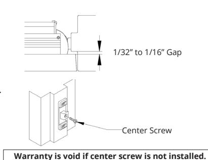
STEP 3: SECURE STRIKE
- 1. Using "A" Mounting Holes, mount strike with 12-24 MS as shown in above drawing. Do not tighten
- 2. Adjust Strike to allow a 1/32" to 1/16" gap between the door face and the edge of stop. Tighten screws.
- 3. Test device operation. Strike may need further adjustment due to door conditions and/or weatherstripping.
- 4. Drill and tap "E" center mounting hole.
- 5. Install 12-24 MS in center of strike.
TROUBLESHOOTING TIPS
O. Device does not lock.
- A. The strike may not be adjusted properly. See step 3.
- The Housing Extrusion must be 1-3/16" from edge of stop. A shim may be required.
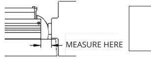
1-3/16": No Shim 1-1/4"· 1 Shim 1-5/16": 2 Shims
Q. Depressing the push bar will not unlock device.
A. - Notched Push Bar End Cap must be installed on the Push Bar end closest to the latch.
Q. Outside key control will not unlock device.
-
A. Nosepiece Key Cam must be parallel to the ledge when installed. See drawing above.
- Tailpiece of the rim cylinder must be in the vertical position.

WWW.LOCKEYUSA.COM
For Technical Support, contact LockeyUSA at support@lockevusa.com or 888.395.0163
Lockey USA PB2500AL ALARM Instructions
STANDARD FEATURES
- Horn factory-set to sound for 90 seconds with automatic reset, or can be field selected to be a continuous horn.
- Audible chirp when turned "ON", Red LED flashes to signal "ON"
PB2500AL:
Powered by 9 Volt Battery with low battery chirp @ 7.5V
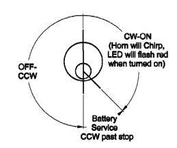
ALARM OPERATION INSTRUCTIONS:
Alarm will sound when push bar is depressed.
ON: Turn key clockwise. Horn will "chirp" once.
The Red LED will blink once every 20 seconds signaling it is armed.
OFF: Turn key counterclockwise one click to disarm.
The Horn will "chirp" intermittently when the battery is low.
See below for instructions to change battery.
After installation, peel and apply label next to alarm cylinder.
BATTERY REPLACEMENT:
- 1. Do not remove Housing End Cap.
- 2. Turn key counterclockwise past the "OFF" position until Key Cylinder stops and hold in position. The alarm is now freed from lock post.
- 3. Slide Alarm Module toward hinge side of door to expose battery.
- 4. Turn key clockwise to center.
- 5. Replace with a 9 Volt Battery.
- 6. Slide Alarm Module toward the Push Bar until it snaps into the locked position.
- 7. Test operation.
TROUBLESHOOTING:
HORN TIME SELECTION
Alarm will not sound when activated:
- Test battery.
ALARM KIT INSTALLATION:
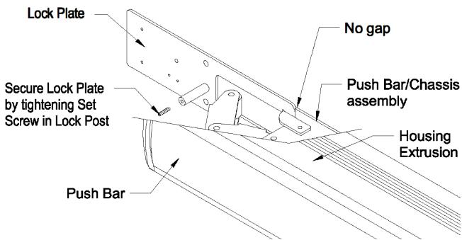
- 1. Slide Lock Plate into bottom grooves of Housing Extrusion and position up flush to Push Bar/Chassis Assembly.
- 2. Secure Lock Plate with Allen Wrench by tightening set screw in post.
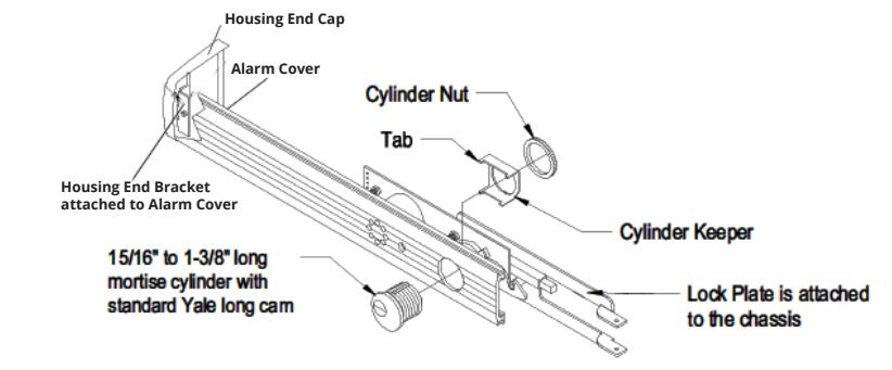
CYLINDER INSTALLATION:
- 1. Remove Yellow Plug in the cylinder hole and discard.
- 2. Remove Key and insert Cylinder as shown.
- 3. Install Cylinder Keeper over Cylinder and secure with Cylinder Nut.
- 4. Remove Housing End Cap from Pack "B". Install Housing End Cap onto Alarm Cover Bracket with 1 each 8-32 3/8" OHPMS Screw.
- 5. Install Alarm Cover into upper grooves of Housing Extrusion and slide towards Push Bar until it snaps into locked position.
Note: The hook on the Alarm Module locks onto the Post of the Lock Plate located in the bottom of the Housing track.
(T)imed 90 seconds, auto reset. (C)onfinuous sound Reset by key. -NC Form C switch on SS2-A option -NO (O) -сом Form C switch on SS1-A & SS2-A options NC On other side of board -NO 12VDC - Terminal for positive voltage of 12 V (#20, #30) 24VDC - Terminal for positive voltage of 24 V -GRD - Negative Terminal Bottom side of alarm
SS1-A Switch Rating: 1.0 A at 30 VDC (Switch is activated by the Push Bar)
SS2-A Switch Rating: 1.0 A at 24 VDC (Switches are deactivated when alarm is in "OFF" positon)
Current draw:
Wiring for SS1-A and SS2-A, 12 or 24 VDC External Power
With alarm sounding: 0.21 ma @ 9 V, 12 V, 24 V In stand by mode: 0.0005 ma @ 9 Volt battery 2.6 ma @ 12 VDC or 24 VDC Observe polarity shown

For Technical Support, contact LockeyUSA at support@lockeyusa.com or 888.395.0163
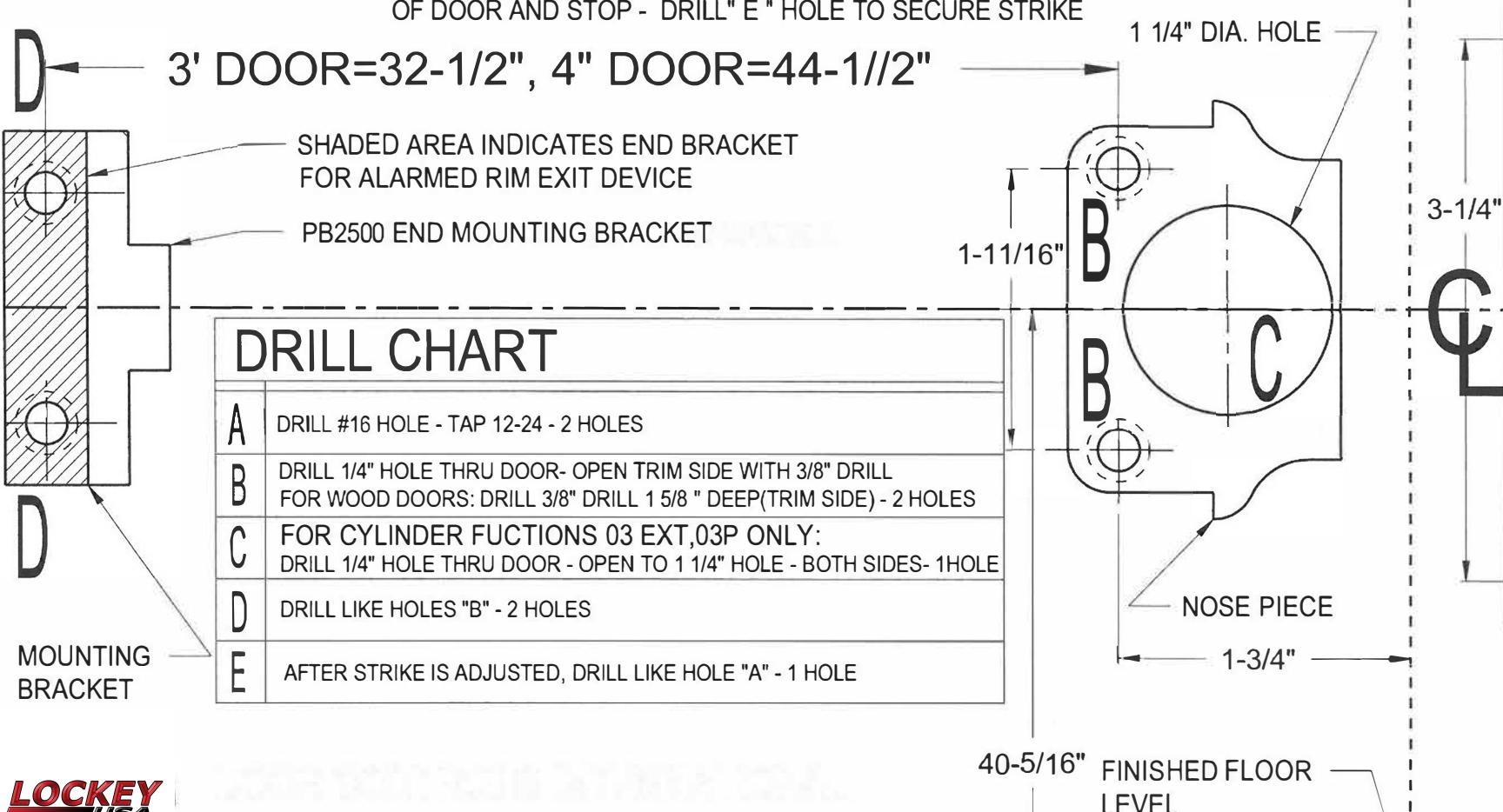
FOLD TOWARDS YOU STRIKE 3-1/4" SOFFIT
PB2500 SERIES RIM PANIC
MOUNTING TEMPLATE FOR SINGLE DOORS

RHR-REVERSE SIDE
IHR
STEP 2- DRILL "A", "B", AND IF NEEDED, "C" HOLES
FINISHED FLOOR
LEVEL
STEP 3- MOUNT PANIC AND STRIKE( SEE INCLUDED SHEET)
STEP 4- LEVEL DEVICE ON DOOR AND DRILL 2 "D" HOLES TO MOUNT END BRACKET
STEP 5- ADJUST STRIKE TO ALLOW 1/32"- 1/16" GAP BETWEEN FACE OF DOOR AND STOP - DRILL" E " HOLE TO SECURE STRIKE
RHR
PB2500 SERIES RIM PANIC
MOUNTING TEMPLATE FOR SINGLE DOORS
LHR-REVERSE SIDE
STEP 1 - DETERMINE HAND OF DOOR, LOCATE FOLD ON FACE OF SOFFIT. TAPE AT A SUGGESTED HEIGHT OF 40 5/16" ABOVE FINISHED FLOOR. BLADE STOPS REQUIRE A NOTCH 1/8"-3/16" DEEP X 2" LONG FOR NOSE PIECE CLEARANCE.
RHR
FOLD
TOWARDS
YOU
STRIKE
SOFFIT
STEP 2- DRILL "A", "B", AND IF NEEDED, "C" HOLES
STEP 3- MOUNT PANIC AND STRIKE( SEE INSTRUCTION SHEET)
STEP 4- LEVEL DEVICE ON DOOR AND DRILL 2 " D " HOLES TO MOUNT END BRACKET
STEP 5- ADJUST STRIKE TO ALLOW 1/32"- 1/16" GAP BETWEEN FACE OF DOOR AND STOP - DRILL" E " HOLE TO SECURE STRIKE