LockeyUSA M230 M230DC Mechanical Lock Instructions Template 1
Open the original PDF document
View PDFDIGITAL M-230 | M230 DC Installation Instructions

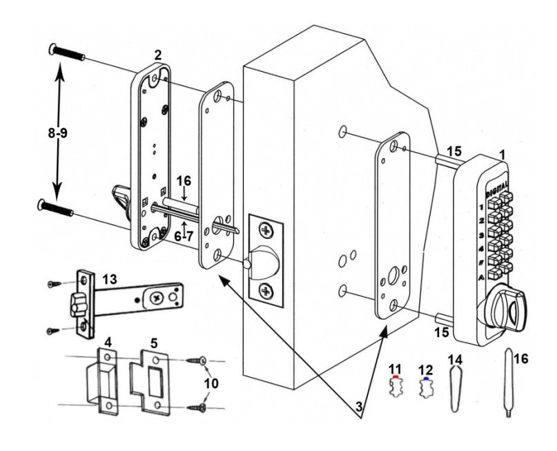
| No. | Part Name | M230 |
|---|---|---|
| 1 | Outside Body | 1 |
| 2 | Inside Body | 1 |
| 3 | Rubber Trim Plate | 2 |
| 4 | Mortised Strike | 1 |
| 5 | Strike Plate | 1 |
| 6 | Spindle 40-55 mm. | 1 |
| 7 | Spindle 30-45mm. | 1 |
| 8 | Machine Screw M4 x 50 mm. | 2 |
| 9 | Machine Screw M4 x 35 mm. | 2 |
| 10 | Wood Screw M4 | 4 |
| 11 | Extra Code Tumblers (Red) | 1 |
| 12 | Extra Non-Code Tumblers (Blue) | 2 |
| 13 | Adjustable Latch 2 3/8" – 2 3/4" | 1 |
| 14 | Tweezers | 1 |
| 15 | Hex Bolts | 2 |
| 16 | Brass Support Pin | 1 |
Step 1: Change User Code ( OPTIONAL )
If you wish to change your code, see instructions on reverse side.
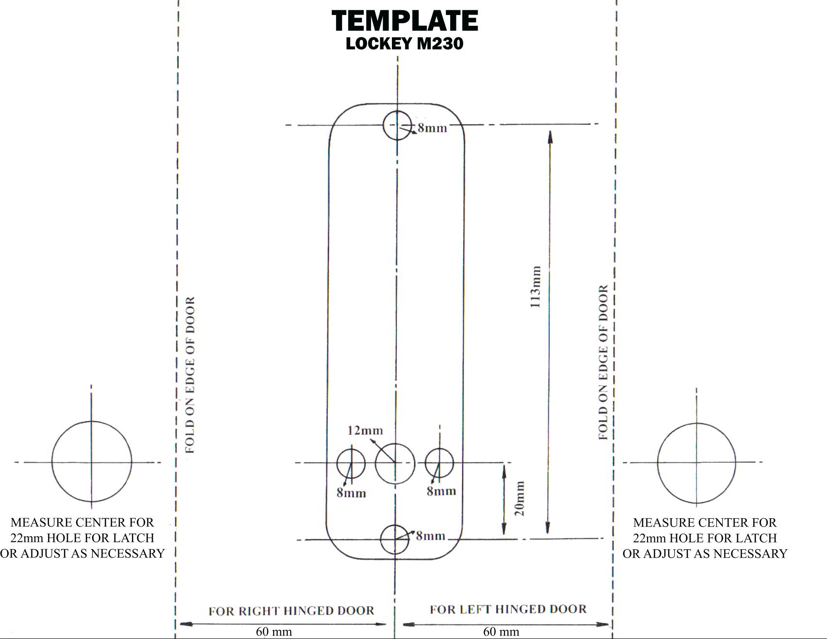
Step 2: Prep Door for Installation with Template
- 1. Place template (supplied) on door and fold along door's edge.
- 2. Mark holes for 2 3/8" or 2 3/4" backset.
- 3. Drill holes as instructed.
NOTE: For Pre-Prepped 2 1/8" doors, you only need to drill top hole.
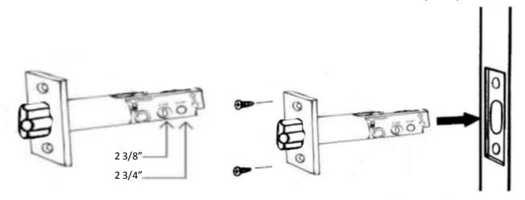
Step 3: Adjust Latch ( if necessary ) & Install
- 1. Adjustable latch (#13) is factory preset for a 2 3/8" backset.
- 2. For 2 3/4" backsets, slide the Cam assembly on the latch to 2 3/4".
- 3. Insert latch into door and secure with Wood Screws (#10).
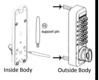
Step 4: Install Support Pin & Hex Bolts
Install Brass Support Pin (#16) into Inside Body as shown in the figure to the Right [Left].
Install/screw Hex Bolts (#15) into the top and bottom of the Outside Body as shown in the figure [Far Right].
Step 5: Verify Correct Spindle Length
- 1. With latch (#13) installed, hold the Inside Body (#2) and Rubber Trim Plate (#3) to the door. Thumb-Turn
- 2. Place Spindle (#6/7) through latch, into the Inside Body, as far as possible.
- 3. Spindle should extend from exterior of door 3/8" min. – 5/8" max.
- 4. If the 30-45 mm (#7) is too long, cut it to the correct length. IMPORTANT: If spindle extends less than 3/8" it may not engage the lock. If spindle extends more than 5/8", it will cause the lock to bind.
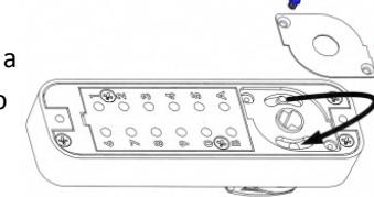
Step 6: Determine Knob Turn Direction ( to unlock )
The lock is preset to unlock when turned clockwise after combination is entered.
If desired, you can unlock the door with a counter-clockwise turn. Remove the two blue screws and move the pin to the opposite side as shown.
Inside Body (#2)
Door Edge
3/8" to 5/8"
Spindle (#5/6)
*M230 DC – Inside Body pin must on opposite side from Outside Body.
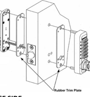
Step 7: Install the DIGITAL M230
1. Place the Rubber Trim Plate (#3) on the backside of the Outside Body (#1).
- 2. Place the Outside Body on the door. The hexagonal bolts (#15) should extend into the top and bottom holes.
- 3. The Support Pin (#16) on the Inside Body should fit into and extend through the hole in the Latch (#13).
INSTRUCTIONS CONTINUED ON REVERSE SIDE
Step 7 cont: Install the DIGITAL M230
- 1. Insert the Spindle (#6/7) into the Outside Body (#1) ensuring it's in the proper angled position. *( SEE FIGURES BELOW )
- 2. Using a screwdriver, secure the lock to the door with the Screws (#8 or #9). Screw length is dependent on door thickness .
- 3. Test the operation of the Latch by turning the inside thumb-turn.
- 4. Locate position where Latch strikes door frame and install Mortised Strike (#4) and Strike Plate (#5).
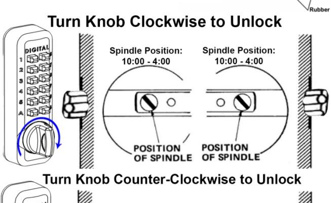
*IMPORTANT: SPINDLE POSITION/ANGLE
CLOCKWISE TURN TO UNLOCK WITH COMBINATION
The M230 is factory preset to unlock with a clockwise turn when the combination is entered. The Spindle MUST be placed through the latch, at a 10:00 – 4:00 angle as shown.
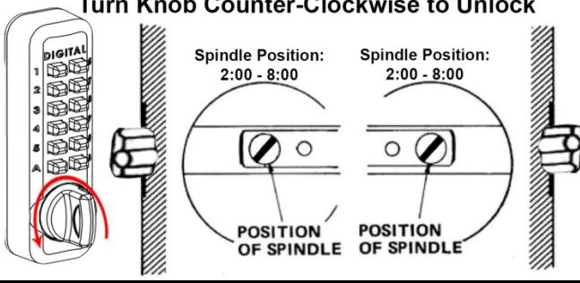
COUNTER-CLOCKWISE TURN TO UNLOCK WITH COMBINATION
If desired, the M230 can be unlocked with a counter-clockwise turn when the combination is entered. To unlock the M230 with a counter-clockwise turn, please refer to Step 6 to change the Handing Pin.
After changing the Handing Pin, the Spindle MUST be placed through the latch at a 2:00 – 8:00 angle as shown.
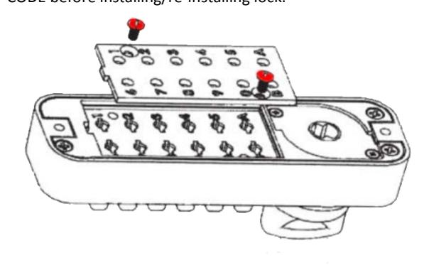
DIGITAL M-Series How to Change Code
- 1. Using a #2 screwdriver, remove the two (2) Red Screws.
- 2. Carefully remove cover plate. WARNING: Springs are attached to plate.
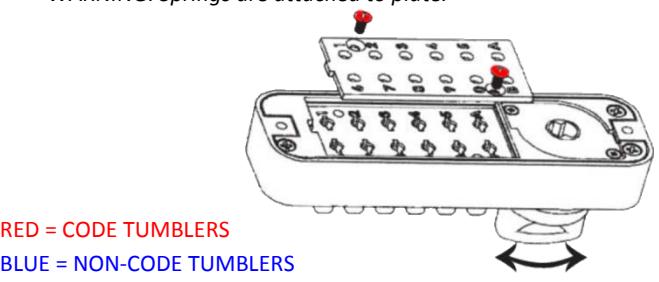
3. TURN & HOLD thumb-turn to right or left to release tumblers. IMPORTANT: THUMB-TURN MUST be turned and held when removing and inserting tumblers. Failure to do so will damage the lock and void the warranty.

RED = CODE TUMBLERS
Do NOT force tumblers into position!
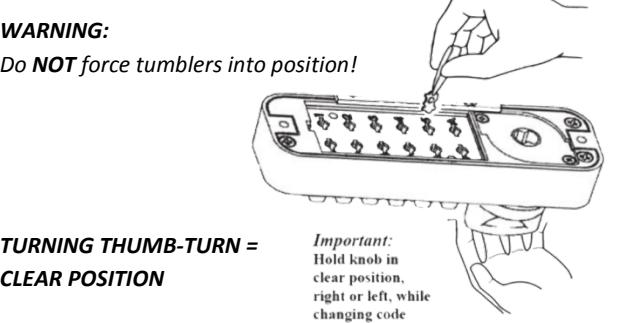
4. With the thumb-turn held to right or left, remove/add CODE (Red) and NON-CODE (Blue) Tumblers to create your desired code.
Ex: 3 Red = 3-Digit Code / 6 Red = 6-Digit Code
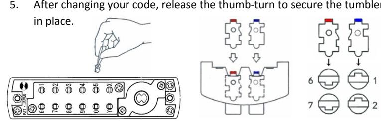
IMPORTANT: Ensure notched side of tumbler fits into slot. (Below – Far Right).
5. After changing your code, release the thumb-turn to secure the tumblers
- 6. Replace the cover plate and secure with two (2) Red Screws, using a #2 screwdriver.
- 7. TEST CODE before installing/re-installing lock.