LockeyUSA M210EZ Mechanical Lock Instructions Updated 12.23.15 Compressed 1
Open the original PDF document
View PDF

DIGITAL M210EZ DEADBOLT INSTALLATION INSTRUCTIONS
Fig. 1
RIGHT HAND
HINGÉ
M210EZ | M210EZDC
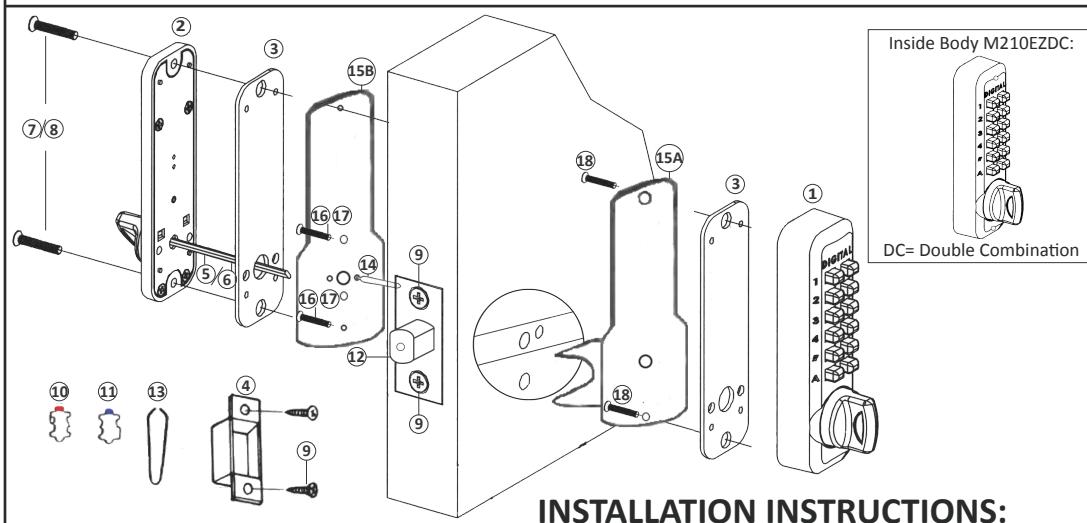
| No. | Part Name | M210EZ |
|---|---|---|
| 1 | Outside Body | 1 |
| 2 | Inside Body | 1 |
| 3 | Rubber Trim Plate | 2 |
| 4 | Mortised Strike | 1 |
| 5 | Spindle 40-55mm. | 1 |
| 6 | Spindle 30-45mm. | 1 |
| 7 | Machine Screw M4 x 12mm | 2 |
| 8 | Machine Screw M4 x 25mm (DC) | 2 |
| 9 | Wood Screw M4 | 4 |
| 10 | Extra Code Tumblers (Red) | 1 |
| 11 | Extra Non-Code Tumblers (Blue) | 2 |
| 12 | Adjustable Deadbolt 2 3/8" - 2 3/4" | 1 |
| 13 | Tweezers | 1 |
| 14 | Brass Support Pin | 1 |
| 15 | EZ Mounting Plates (A&B) | 2 |
| 16 | Machine Screw M4 x 35mm | 2 |
| 17 | Machine Screw M4 x 17mm | 2 |
| 18 | Machine Screw M5 x 1/2" | 2 |
Fig. 2
LEFT HAND
Step 1: Change User Code/Combination (OPTIONAL)
To change user code/combination, see instructions on reverse side.
Step 2: Identify Door Handing
(The M210EZ is pre-handed for right-hand doors)
Right-Hand Doors – From exterior of door, hinges are on right-side (Fig. 1). Left-Hand Doors – From exterior of door, hinges are on left-side (Fig. 2).
To change handing for left-hand doors, use a #1 phillips screwdriver to remove two blue screws and cover plate from Outside Body (Fig. 3).
Move the handing pin from the right side of the Outside Body to the hole on the left side. Replace plate and screws.
*M210EZDC – Inside Body must be handed opposite from Outside Body.
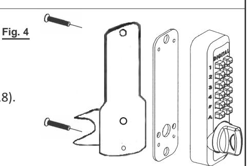
Step 3: Place Outside Body on EZ Plate A
Place Rubber Trim Plate (#3) on EZ Plate A (#15).
Place the Outside Body (#1) on EZ Plate A and screw into place with two (2) M5 x 1/2" screws (#18).
Step 4: Install Brass Support Pin (Fig. 5)
Install Brass Support Pin (#14) into EZ Plate B (#15) on either side.
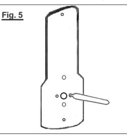
Fig. 3
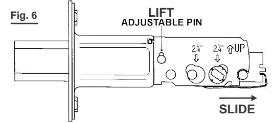
Step 5: Adjust Deadbolt (if necessary) & Install
Adjustable Deadbolt (#12) is preset to 2 3/8" backset.
To adjust, lift pin and slide to 2 3/4" (Fig. 6).
With arrow pointed UP, insert Deadbolt and secure with two (2) Wood Screws (#9).
Continued on Reverse Side
INSTALLATION INSTRUCTIONS CONTINUED:
Step 6: Attach EZ Plates
Place EZ Plate A (#15) with Outside Body attached to outside of door.
Place EZ Plate B (#15) to the inside of the door making sure the
Brass Support Pin fits through the hole in the deadbolt.
Hold tight to door and secure plates together using two (2) M4 x 17mm. (#17) or M4 x 35mm. screws (#16).
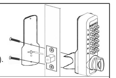
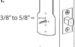
Step 7: Verify Spindle Length
Insert the Spindle (#5 or #6) at the correct angle (below) into the large hole in EZ Plate B, through the deadbolt and into the Outside Body. Spindle should extend from interior of door 3/8" min. to 5/8" max.
If the 30-45mm spindle (#6) is too long, cut it to the correct length.
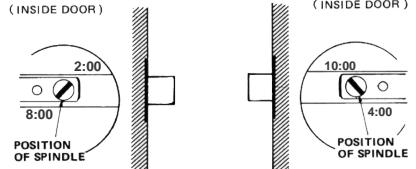
*IMPORTANT: SPINDLE POSITION/ANGLE:
RIGHT-HAND DOORS: From inside, place spindle through Deadbolt, into the Outside Body (#1) in the 2:00/8:00 position. LEFT-HAND DOORS: From inside, place spindle through Deadbolt, into the Outside Body (#1) in the 10:00/4:00 position.
*IMPORTANT:
If spindle extends less than 3/8" it may not engage the lock. If spindle extends more than 5/8", it will cause the lock to bind.
Step 8: Complete Installation and Test Lock
Place Rubber Trim Plate to EZ Plate B (#15).
Place Inside Body to EZ Plate B and secure using two screws (M4 x 12mm (#7) for single combination, M4 x 25mm (#8) for DC).
Test your M210EZ Digital Door Lock before closing the door:
From Inside: Turn knob to lock, turn knob to unlock. For M210EZDC, use code to unlock.
From Outside: Turn knob to lock, use combination to unlock.
* NOTE: If combination is needed to lock, change handing (as described in Step #3).
Locate position where Deadbolt strikes door frame and install Mortised Strike (#4).
Your installation is now complete.
How to Change User Code/Combination
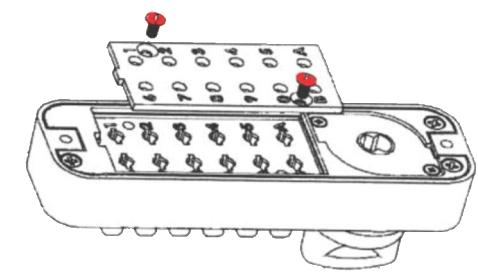
- 1. Using a #2 screwdriver, remove the two (2) Red Screws.
- 2. Carefully remove cover plate.
SAVE
WARNING: Springs are attached to plate.
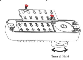
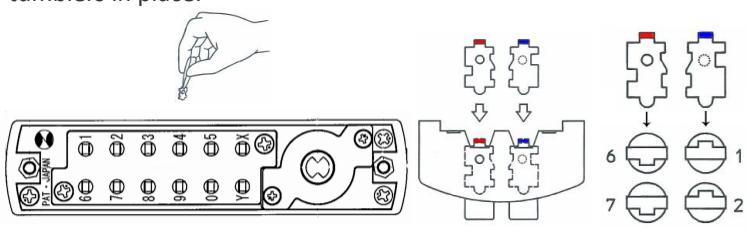
3. TURN & HOLD thumb-turn to right or left 90° to release tumblers. IMPORTANT: THUMB-TURN MUST be turned 90°and held when removing and inserting tumblers. Failure to do so will damage the lock and void the warranty.
WARNING:
Do NOT force tumblers into position!
TURNING THUMBTURN 90°= CLEAR POSITION.
4. With the thumb-turn held 90° to right or left, remove/add CODE (Red) and NONCODE (Blue) tumblers to create the desired code. Ex: 3 Red = 3-Digit Code / 6 Red = 6-Digit Code
5. After changing your code, release the thumb-turn to secure the tumblers in place.
6. Replace the cover plate and secure with two (2) Red Screws, using a #2 screwdriver.
7. TEST CODE before installing/re-installing lock.
For more helpful tips and installation instructions, visit www.LOCKEYUSA.com