LockeyUSA GM270 Gemini M Installation Mechanical Lock Instructions
Open the original PDF document
View PDFInstallation Template
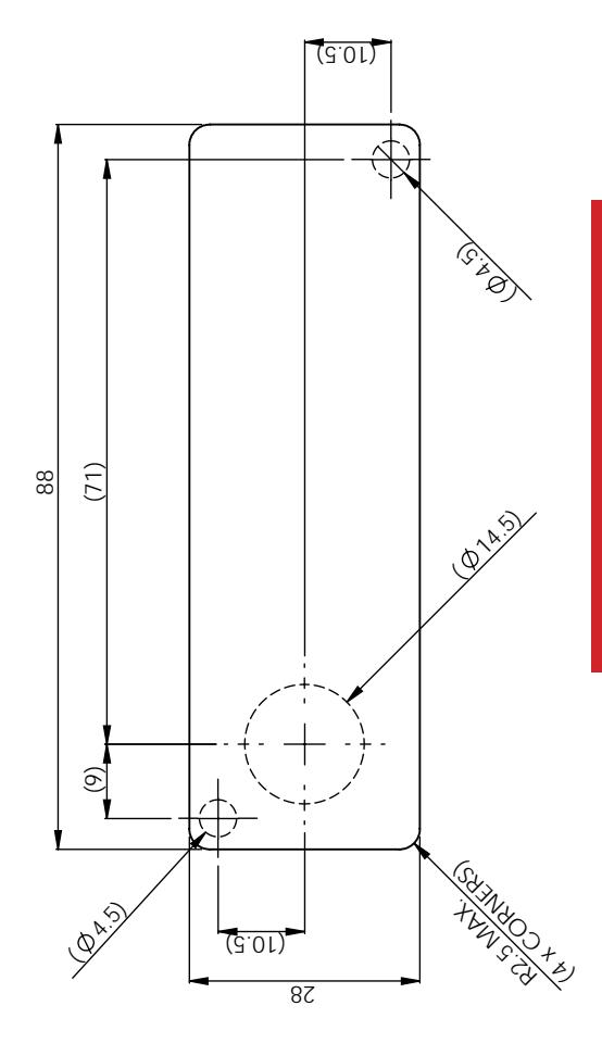
Please check that template is correct size before use – copies can be distorted

INSTALLATION INSTRUCTIONS
GM270 - Gemini Mechanical
IMPORTANT NOTE
For surface mount option, use 3 x hole positions For flush fit option, use rectangular aperture (88mm x 28mm)
LockeyUSA 4245 S. Lincoln Rd. Mt. Pleasant, MI 48858
T: 888.395.0163 F: 989.772.1936
E: info@lockeyusa.com W: www.lockeyusa.com

www.lockeyusa.com/GM270
INSTALLATION INSTRUCTIONS GM270 - Gemini Mechanical
The Gemini can be installed in two ways:
- Surface Mount
- Flush Mount
Surface Mount
- Step 1 Remove all packaging.
- Step 2 Fit the surface mount sleeve to lock as shown in Picture 1.
- Step 3 Position the lock on the outside of the door as shown in Picture 2.
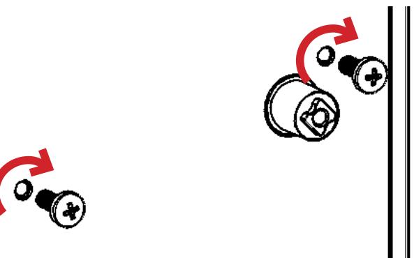
- Step 4 Holding the lock in position, fit the 2 x M4 pan head screws (supplied with the surface mount sleeve) as shown in Picture 3.
- Step 5 Tighten the 2 x M4 screws to 1Nm.
- Step 6 Position the cam onto the rear of the lock as required, fit the cam washer and fixing screw as shown in Picture 6.
- Step 7 Tighten the cam fixing screw using a screwdriver to 1.5Nm. Take care not to damage the screw thread when fitting the screw.
- Step 8 Before closing the door, test the lock by selecting the correct User Code and rotating 90°.
- Step 9 Your lock should now be ready to use.
Flush Mount
- Step 1 Remove all packaging.
- Step 2 Position the lock on the outside of the door as shown in Picture 4.
- Step 3 Holding the lock in position, fit the clamp box and 2 x M4 pan head screws (supplied with the clamp box) as shown in Picture 5.
- Step 4 Use a screwdriver to tighten the 2 x M4 screws to 1Nm.
- Step 5 Position the cam onto the rear of the lock as required, fit the cam washer and fixing screw as shown in Picture 6.
- Step 6 Tighten the cam fixing screw using a screwdriver to 1.5Nm. Take care not to damage the screw thread when fitting the screw.
- Step 7 Before closing the door, test the lock by selecting the correct User Code and rotating 90°.
- Step 8 Your lock should now be ready to use.
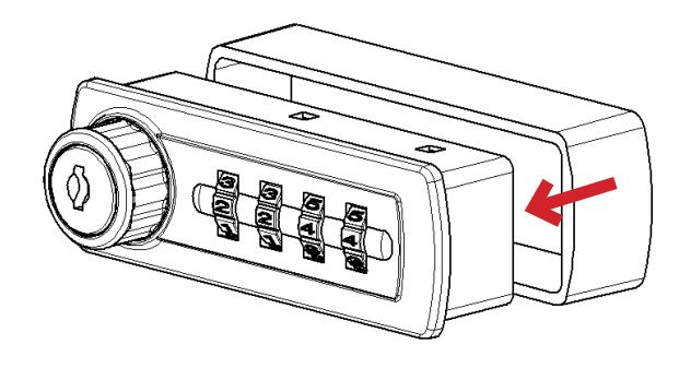
Picture 1. Fit surface mount sleeve to lock as shown.
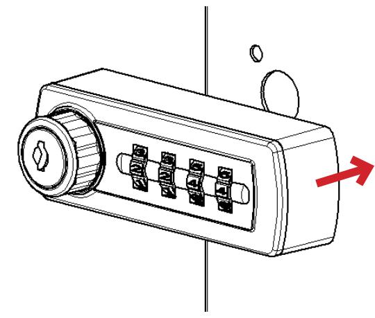
Picture 2. Position lock on door panel as shown.
Picture 3.
Fit 2 x M4 pan head screws as shown.
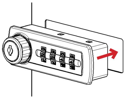
Picture 4. Position lock through door panel as shown.
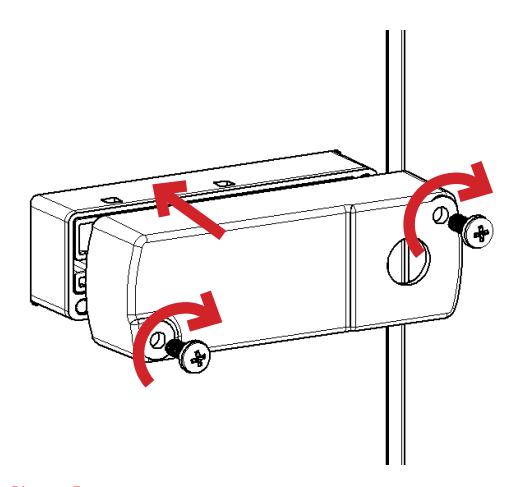
Picture 5. Fit clamp box and 2 x M4 pan head screws as shown.
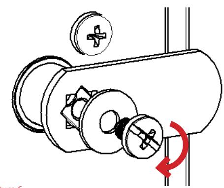
Picture 6. Fit cam, washer & screw. Tighten.