LockeyUSA GE370 Gemini Installation Electronic Lock Insrtuctions
Open the original PDF document
View PDFStep 1 Remove all packaging.
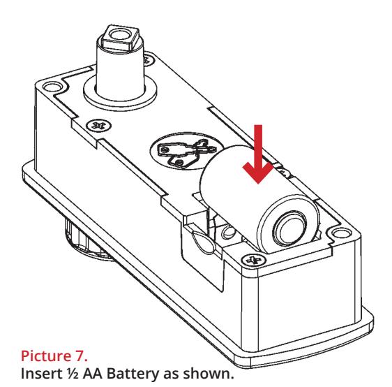
Step 2 Insert Battery 1/2AA. As shown in Picture 7.
Positive facing out as per ' + ' sign on inside battery case.
Step 3 Secure battery with Battery Lid as per picture 8. Click into position.
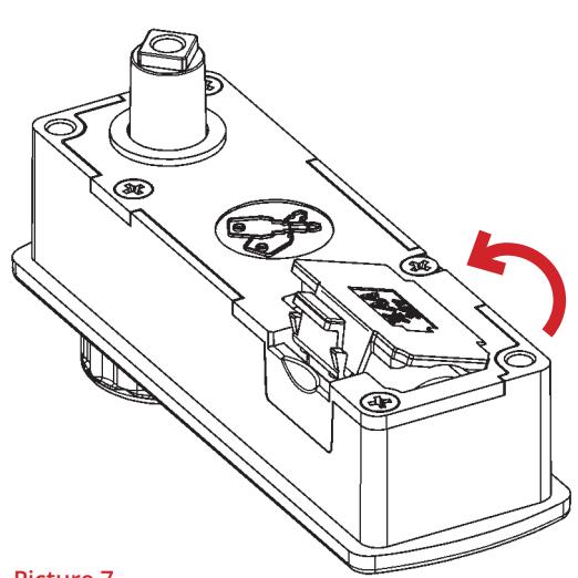
Picture 7. Fit Battery Lid as shown click in place.
Important Note: Inserting Battery
Before drilling holes, please ensure that the position of the lock when installed will allow clearance for the cam to function.
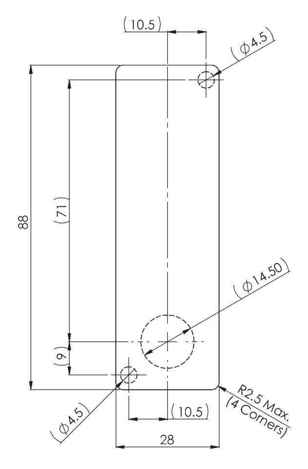
For surface mount option, use 3 x hole positions For flush fit option, use rectangular aperture (88mm x 28mm)
IF USING A PRINTED TEMPLATE ENSURE THAT THE TEMPLATE IS THE CORRECT SIZE AS PRINTERS VARY
LockeyUSA 4245 S. Lincoln Rd. Mt. Pleasant, MI 48858
T: 888.395.0163 F: 989.772.1936 E: info@lo ckeyusa.com
W:www .lockeyusa.com


INSTALLATION INSTRUCTIONS
GE370 - Gemini Electronic
www.lockeyusa.com/GE370
INSTALLATION INSTRUCTIONS
GE370 - Gemini Electronic
Special Notes
Before installing the Gemini Electronic, load the battery and familiarize yourself with the operation and programming. The lock is supplied in PUBLIC operating mode with a four-digit code.
The lock can be opened at any time using the Master Code.
Unless manufactured to special order, the default Master Code is 11 33 55 77 and the default User Code is 22 44. These codes are common to all standard locks and it is very important that you set your own personal Master and User Codes. Your lock is not secure until you have changed the default Master Code and User Code.
Keep a safe record of your master code as it is not possible to make any programming changes without it.
Please see programming guide to set your own codes.
The GE370 lock can be installed in two ways:
- •Flush Mount
- •Surface Mount
Surface Mount
- Step 1 Remove all packaging.
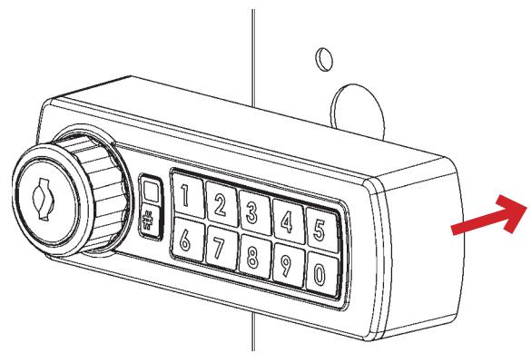
- Step 2 Fit the surface mount sleeve to lock as shown in Picture 1.
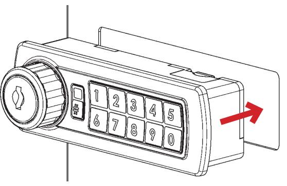
- Step 3 Position the lock on the outside of the door as shown in Picture 2.
- Step 4 Holding the lock in position, fit the 2 x M4 pan head screws (supplied with the surface mount sleeve) as shown in Picture 3.
- Step 5 Tighten the 2 x M4 screws to 1Nm.
- Step 6 Position the cam onto the rear of the lock as required, fit the cam washer and fixing screw as shown in Picture 6.
- Step 7 Tighten the cam fixing screw to 1.5Nm. Take care not to damage the screw thread when fitting the screw.
- Step 8 Before closing the door, test the lock by selecting the correct User Code and rotating 90°.
- Step 9 Your lock should now be ready to use.
Flush Mount
- Step 1 Remove all packaging.
- Step 2 Position the lock on the outside of the door as shown in Picture 4.
- Step 3 Holding the lock in position, fit the clamp box and 2 x M4 pan head screws (supplied with the clamp box) as shown in Picture 5.
- Step 4 Tighten the 2 x M4 screws to 1Nm.
- Step 5 Position the cam onto the rear of the lock as required, fit the cam washer and fixing screw as shown in Picture 6.
- Step 6 Tighten the cam fixing screw to 1.5Nm. Take care not to damage the screw thread when fitting the screw.
- Step 7 Before closing the door, test the lock by selecting the correct User Code and rotating 90°.
- Step 8 Your lock should now be ready to use.
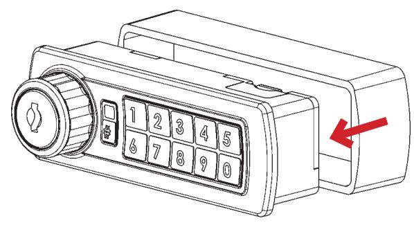
Picture 1. Fit surface mount sleeve to lock as shown.
Picture 2. Position lock on door panel as shown.
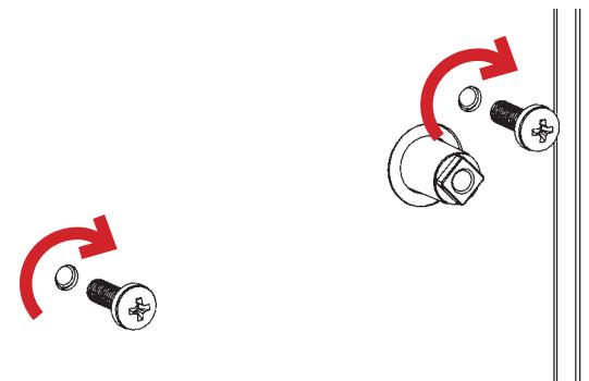
Picture 3. Fit 2 x M4 pan head screws as shown.
Picture 4. Position lock through door panel as shown.
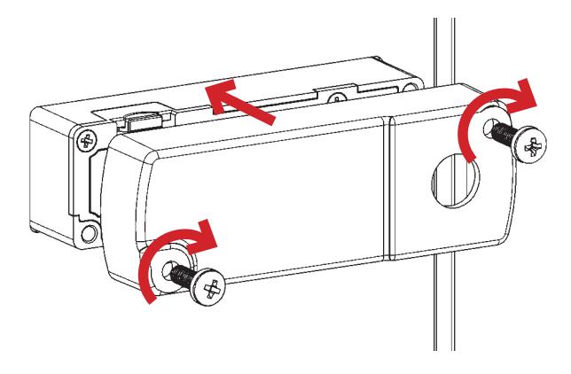
Picture 5. Fit clamp box and 2 x M4 pan head screws as shown.
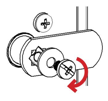
Picture 6. Fit cam, washer & screw. Tighten.