LockeyUSA EB915 Installation Electronic Lock Instructions
Open the original PDF document
View PDFELECTRONIC DEADBOLT
Installation Guide

⚠ WARNING
Do not use an electric screwdriver during installation.
⚠ WARNING
This Manufacturer advises that no lock can provide complete security by itself. This lock may be defeated by forcible or technical means, or evaded by entry elsewhere on the property. No lock can substitute for caution, awareness of your environment, and common sense. Builder's hardware is available in multiple performance grades to suit the application In order to enhance security and reduce risk, you should consult a qualified locksmith or other security professional.
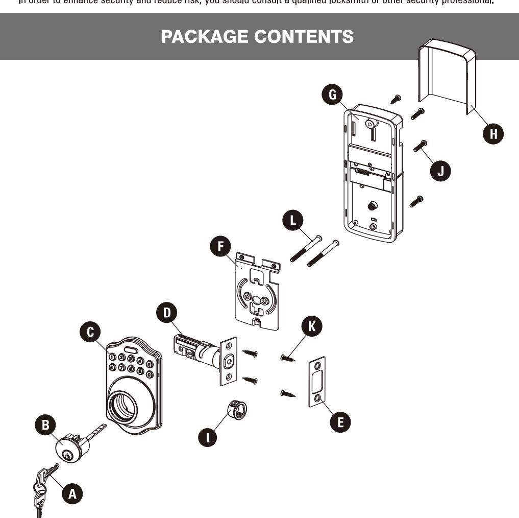
| Part | Description | Quantity |
|---|---|---|
| Α | Key | 2 |
| В | Cylinder | 1 |
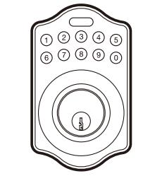
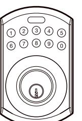
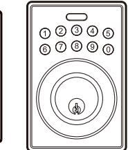
| С | Deadbolt Keypad Assembly | 1 |
| D | Deadbolt Latch | 1 |
| Part | Description | Quantity |
|---|---|---|
| Е | Strike Plate | 1 |
| F | Mounting Plate | 1 |
| G | Receiver Assembly | 1 |
| Н | Battery Cover | 1 |
| I | Drive-in Sleeve (Optional) | 1 |
HARDWARE SCREWS CONTENTS


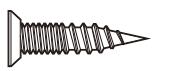

Wood Screws Qty. 5


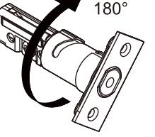
LATCH ADJUSTMENT
Determine if the latch needs to be adjusted to the 2-3/4" (70 mm) backset. To adjust, rotate the latch until it stops.

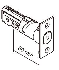
2-3/8" (60 mm)
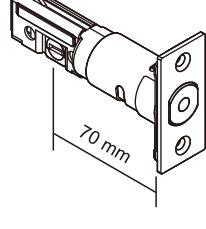
2-3/4" (70 mm)
CHANGE LATCH FACE
Determine which latch mounting method will be used and make necessary adjustments.
No adjustment required for square latch face plate. a. Use a flat screwdriver to separate the face plate. b. Snap selected latch face onto back plate.
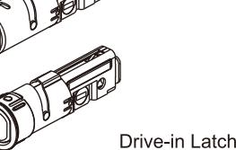
Drive-in Installation
Remove original latch faceplate.
Align the drive-in sleeve as illustrated and snap into the latch case.
Backset Determination
Backset is a distance from door edge to centre of hole on door face. Adjustable latch fits both backset of 2-3/8" (60 mm)
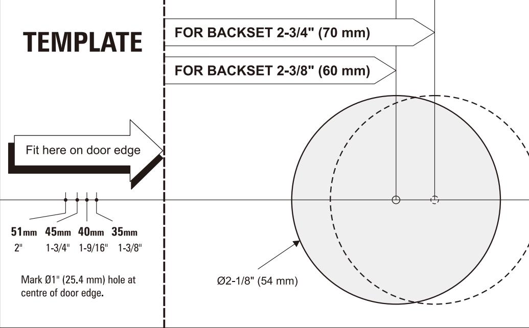
Mark the Door with Template
and 2-3/4" (70 mm).
Select the height and backset as desired on the door face; use the TEMPLATE as an indication to mark the centre of the circle on the door face and the centre of the door edge.
Drill Holes
Using the marks as a guide to drill a hole Ø2-1/8" (54 mm) through the door face for the lockset, then a hole of Ø1" (25.4 mm) for latch.
Install Latch
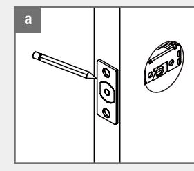
Insert the latch and ensure it is parallel to the door face. Mark the outline of the faceplate, then take out the latch.
You need to stay this way up when inserting the latch.
Chisel 5/32" (4 mm) deep along the outline to allow the faceplate to be aligned with the door edge.
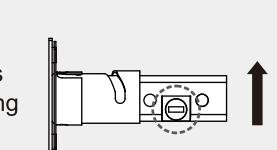
Insert the latch into the door. Use 2 wood screws to secure Please do not fully tighten the
screws until lock is
completely installed.
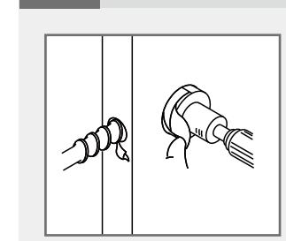
Install Drive-in Latch Drive the latch into the hole on edge of door.
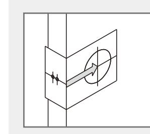
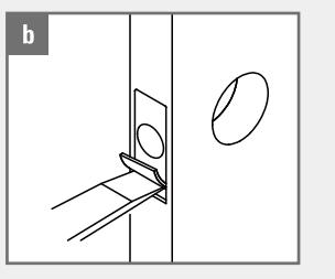
Install Strike
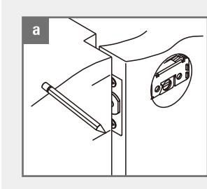
To identify the centre of strike: close the door to lay the latchbolt against the door frame.
Mark the centre line on the doorframe exactly opposite the latch hole in the door edge.
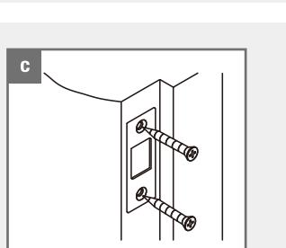
Install the strike plate into your door frame and tighten with wood screws.
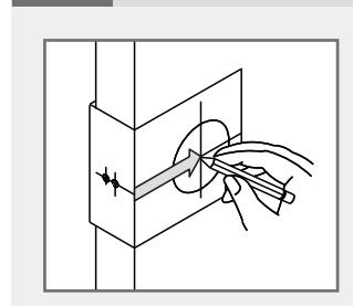
Install cylinder into the deadbolt keypad assembly with tailpiece in
hub of the latch.
horizontal position inserted through
Install Keypad Assembly
vertical line of strike.
Chisel 5/64" (2 mm) deep along the strike outline to allow the strike to be aligned with the doorframe.
Pass the IC wire under the latch to
the interior side of the door.
Measure one half of door thickness from door stop and vertically mark centre line of strike.
Drill 1" (25.4 mm) hole, 1" (25.4 mm) deep at intersection of horizontal and
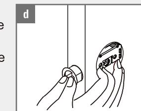
Install Receiver Module
Adjust Thumb Turn Piece
Rotate the thumb turn piece to the LEFT
Rotate the thumb turn piece to the RIGHT
at 45 degrees for right-handed doors.
at 45 degrees for left-handed doors.
Note: The thumb turn piece is opposite to the latching side.
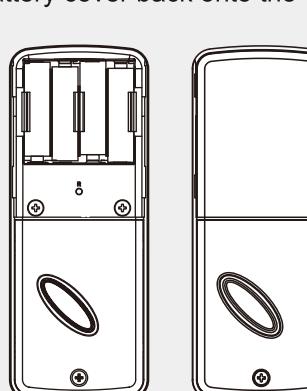
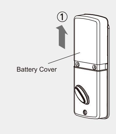
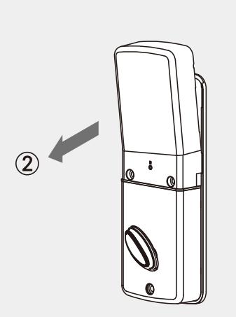
Remove the battery cover (push it up first then pull it out).
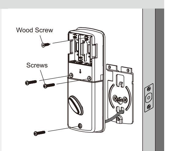
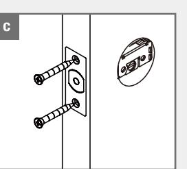
Connect the IC wire into the back of the receiver module. Ensure that the deadbolt tailpiece is engaged with turn piece, then attach receiver module to the door with
Use the optional wood screw to secure the receiver module to wood doors only.
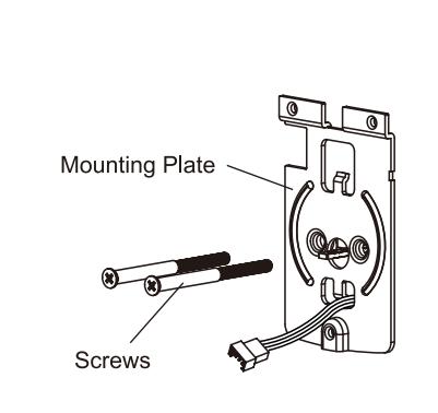
Install Inside Mounting Plate
Identify Door Handing
The door is left-handed if the hinges are on the left side of the door,
Hinge
Face the door from the outside.
Pass the IC wire through the wire hole of the mounting plate.
Fix the mounting plate with screws. If outside lock assembly is lopsided, please loosen the screws to adjust its position and tighten the screws again.
Left-handed
Insert Batteries
Insert 4 (AA) 1.5 V alkaline batteries and slide the battery cover back onto the receiver module.
Remarks:
(1) Alkaline batteries are recommended in order to stabilize the power supply. If you don't use alkaline, battery performance will be reduced greatly.
(2) All settings will be retained in the memory even if the batteries are completed dead.