LockeyUSA Digital Deadbolt 2210 Mechanical Lock Instructions Template 1
Open the original PDF document
View PDF

DIGITAL 2210 Deadbolt Installation Instructions
2210 | 2210 DC
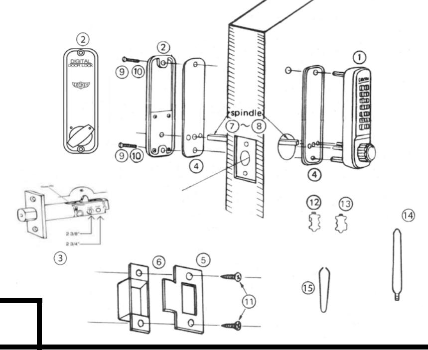
| No. | Part Name | 2210 |
|---|---|---|
| 1 | Outside Body | 1 |
| 2 | Inside Body | 1 |
| 3 | Adjustable Deadbolt (2 3/8" – 2 3/4") | 1 |
| 4 | Rubber Trim Plate | 2 |
| 5 | Strike Plate | 1 |
| 6 | Mortised Striker | 1 |
| 7 | Spindle 40-55 mm. | 2 |
| 8 | Spindle 30-45 mm. | 2 |
| 9 | Machine Screw M4 x 50 mm. | 4 |
| 10 | Machine Screw M4 x 35 mm. | 1 |
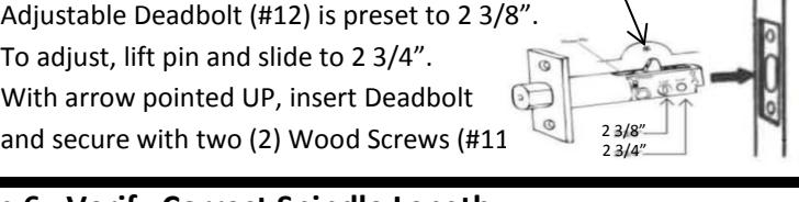
| 11 | Wood Screw M4 | 2 |
| 12 | Non-Combination Tumbler | 1 |
| 13 | Combination Tumbler | 3 |
| 14 | Brass Support Pin | 2 |
| 15 | Tweezers | 1 |
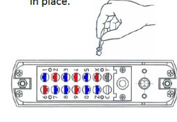
Step 1: Change User Code ( OPTIONAL )
If you wish to change your code, see instructions on reverse side.
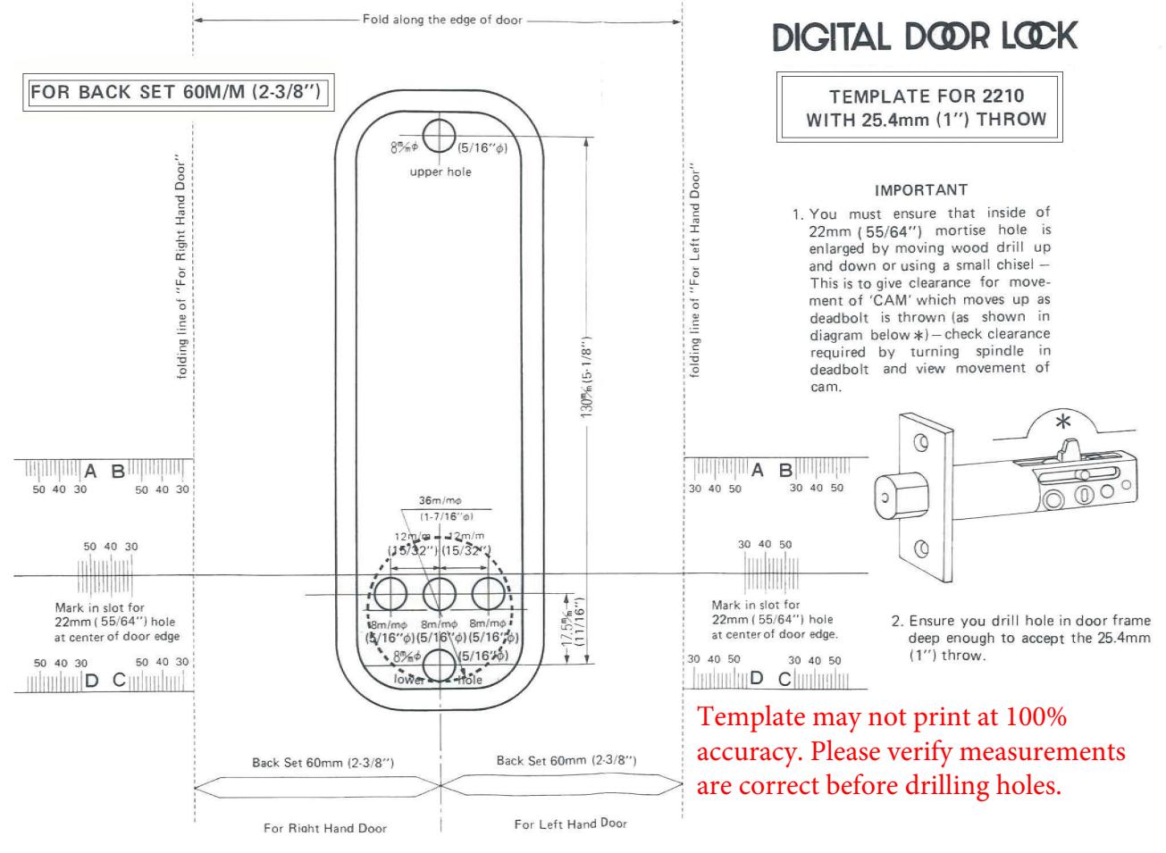
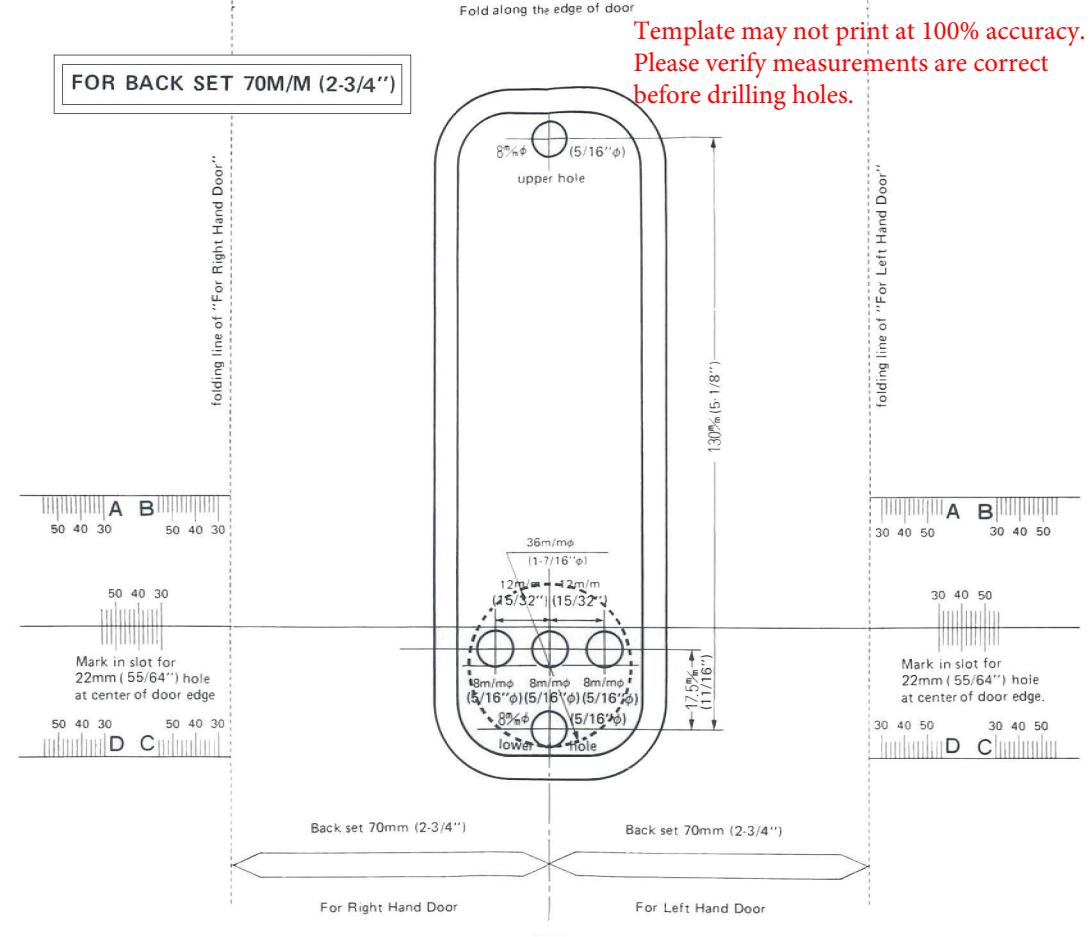
Step 2: Prep Door for Installation with Template
- 1. Place template (supplied) on door and fold along door's edge.
- 2. Mark holes for 2 3/8" or 2 3/4" backset.
- 3. Drill holes as instructed.
NOTE: For Pre-Prepped 2 1/8" doors, you only need to drill top hole.
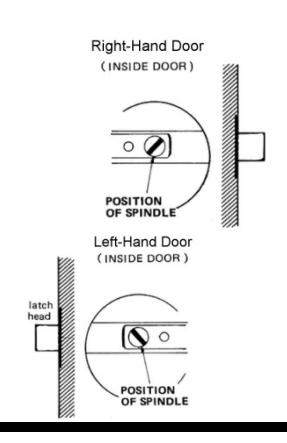
Step 3: Identify Door Handing
Right-Hand Doors – From exterior of door, hinges are on right-side. (Fig. 1)
Left-Hand Doors – From exterior of door, hinges are on left-side. (Fig. 2)
The 2210 is factory pre-handed for right-hand doors. To change handing, remove two blue screws and cover plate from Outside Body.
Now, move the pin from the right side of the outside body to the hole on the left side. Replace plate and screws.
*2210 DC – Inside Body handing pin must be placed on opposite side from Outside Body.
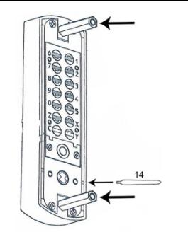
Step 4: Install Support Pin & Hex Bolts
Install Brass Support Pin (#14) into either hole on Outside Body as shown in the figure to the Right [Left].
Install/screw Hex Bolts into the top and bottom of the Outside Body as shown in the figure (Far Right).
Step 5: Adjust Deadbolt (if necessary) & Install
1. Adjustable Deadbolt (#12) is preset to 2 3/8".
2. With arrow pointed UP, insert Deadbolt
Inside Knob
Step 6: Verify Correct Spindle Length
1. With deadbolt (#3) installed, hold the Inside Body (#2) and Rubber Trim Plate (#4) to the door. Inside Body (#2)

3. Spindle should extend from exterior of door 3/8" min. – 5/8" max.
4. If the 30-45 mm (#8) is too long, cut it to the correct length. IMPORTANT: If spindle extends less than 3/8" it may not engage the lock. If spindle extends more than 5/8", it will cause the lock to bind.
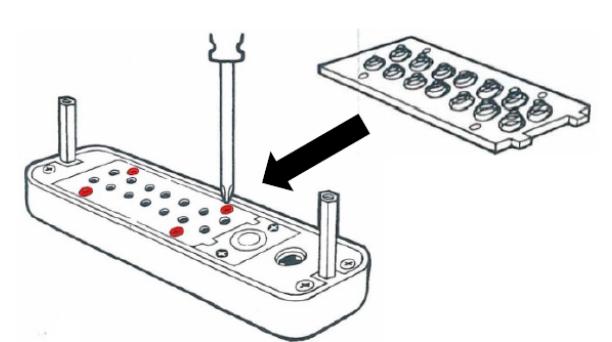
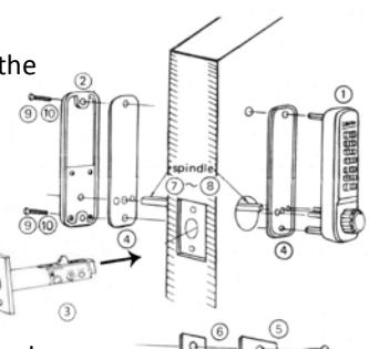
Step 7: Install the DIGITAL 2210
5. Place the Rubber Trim Plate (#4) on the backside of the Outside Body (#1).
6. Place the Outside Body on the door. The hexagonal bolts should extend into the top and bottom holes.
7. The Support Pin (#14) on the Inside Body should fit into and extend through the hole in the Deadbolt (#3).
INSTRUCTIONS CONTINUED ON REVERSE SIDE
Adj. Pin
Door Edge
3/8" to 5/8"
Spindle (#5/6)
Step 7 cont: Install the DIGITAL 2210
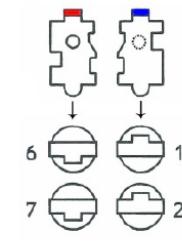
- 1. Insert the Spindle (#7/8) into the Outside Body (#1) ensuring it's in the proper angled position. *( SEE FIGURES BELOW )
- 2. Using a screwdriver, secure the lock to the door with the Screws (#9 or #10). Screw length dependent on door thickness .
- 3. Test the operation of the Deadbolt by turning the inside knob.
- 4. Locate position where Deadbolt strikes door frame And install Mortised Strike (#4).
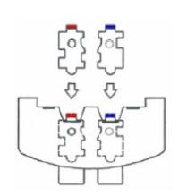
*IMPORTANT: SPINDLE POSITION/ANGLE
RIGHT-HAND DOORS: From inside, place spindle through Deadbolt, into the Outside Body (#1) in the 2:00/8:00 position as shown to right.
LEFT-HAND DOORS: From inside, place spindle through Deadbolt, into the Outside Body (#1) in the 10:00/4:00 position as shown to right.

www.LOCKEYUSA.com
2000 Series How to Change Code