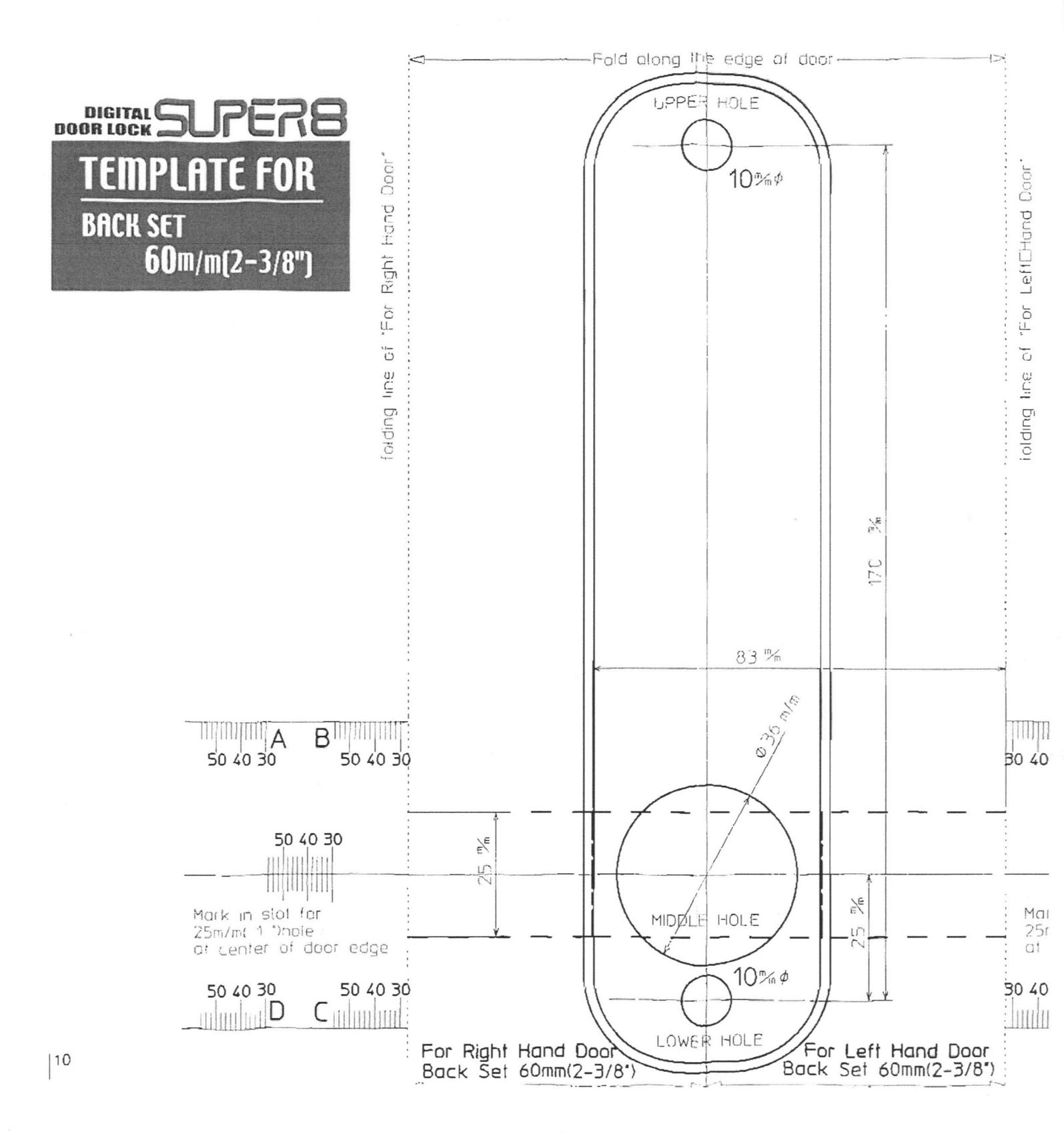
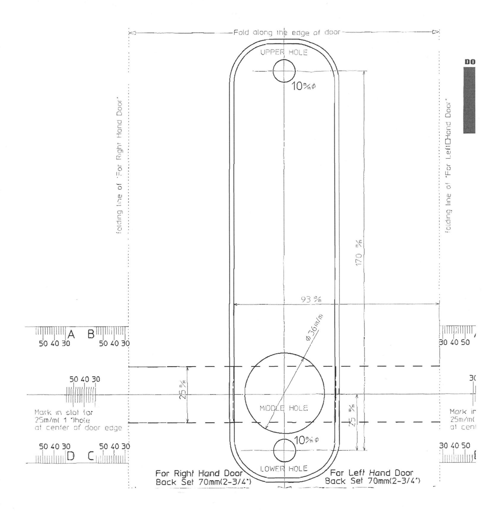
LockeyUSA 7070N Mechanical Mounting Lock Instructions Template 1
Open the original PDF document
View PDFFigure 2: Tail Piece Position


Left Ric
Figure 3: 4580 Cylinder Remove 2 pins
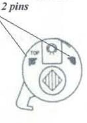
Figure 4:
7070N
This 7070N is a retro fit to replace the key cylinder on your Adams Rite LATCH style door lock. This is only intended to replace the cylinder. If you need the latch or push paddle, you will need to order additional parts.
Mounting Instructions For 7070N Adams Rite Retro fit
- 1). Take out keyed cylinder and replace with the 4580 cylinder, as per instructions for the Adams Rite 4580 mounting guide. Be sure to hand door to right or left.
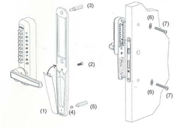
- 2). After the 4580 Adams Rite cylinder has been installed place the square tail piece into the 4580. Note: A right hand and left hand tail piece are supplied. For your application, use the tail piece that is closest to the 6:00; 12:00 position or the most vertical position. See Figure 2.
- 3). After proper tail piece is in place, place the metal trim plate onto door, over the tail piece. Place tail piece center into the center round hole. When trim plate is centered to tail piece mark top and bottom hole with pencil. After holes are marked, drill holes with a 3/8" drill bit. (Note: Do not drill all the way through, rather only through the first wall of door frame.) When holes are drilled in top and bottom of the first wall of outside door post, change your drill bit to a 1/4" drill bit and continue through the inside wall of door post.
- 4). When holes are drilled through door, remove the 2 alignment pins on the 4580. See fig: 3
Now you are ready to install the combination lock.
To mount lock to the trim place these (7) easy steps must be followed (Fig. 4):
- 1. Place trim plate cover to bottom of trim plate position #1
- 2. Place combination lock to trim plate
- 3. Place m5 x 5/8" screw to bottom of lock #2
- 4. Place gold hex screw to top hole in lock #3
- 5. Place silver spacer ring #4 to short silver hex screw #5 and place into bottom hole in trim plate
- 6. Make sure handing and combination are set
- Place digital door lock and trim plate to the door. Make sure tail piece is not too long. If lock bottoms out over the tail piece, you may need to break off the perforated end of tail piece to shorten.
Note: Be sure that the lock and mounting plate is centered over tail piece. It is important that it is mounted very straight. When mounting lock and tail piece is not loose fitting, lock may bind and not work freely.
- 8. Place finish washers (#6) to M 4 x 1 1/4" mounting screws (#7).
- Screw lock into place.
NOTE: TEST LOCK MANY TIMES BEFORE LOCKING THE DOOR TO MAKE SURE LOCK IS SET PROPERLY.
If after pushing the combination and pushing on the lever and the latch does not retract all the way in, you may need to switch the tail piece and test the opposite hand and test.
BEFORE INSTALLING THE DIGITAL DOOR LOCK, 7070N
CONFIRM THE HAND OF OPENING
The lock comes factory set for right hand opening, if your door is hinged on the right from the entry side then proceed to how to install after installing the l support pin as per below. if your door is hinged on the left from the entry side then follow changing the hand of opening to left hand.
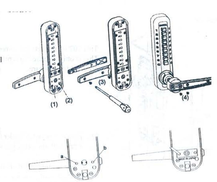
CHANGING THE HAND OF OPENING TO LEFT HAND
•move the screw (1) into position (2)
•remove the two screws (3) from the inside of the handle releasing the handle cover. •remove the two screws (4) that connect the handle to the lock, lift the handle off and reverse it to left hand. replace all screws securely. •repeat the same with the inside handle. •on the entry side of the lock either side of the spindle cog there are two holes (a,b), screw I support pin into the following position for r/h opening and the opposite position for I/h opening.
for right hand
HOW TO CHANGE THE CODE NUMBER
TO PREVENT ANY PROBLEMS OR DAMAGE, READ THE FOLLOW-ING INSTRUCTIONS BEFORE CHANGING YOUR CODE
Hold the front lock body in the horizontal position. remove the 4 red screws and take the lid off carefully
note: there are 9 springs in the back of the lid.
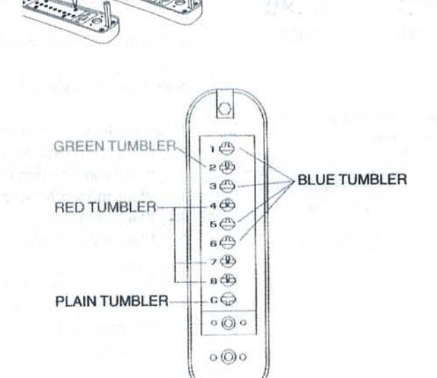
the code tumbler
the green coloured are the tumblers for 'double pushing' the red coloured are the tumbers for 'single pushing' the blue coloured are keyless tumblers 'non-code' the plain tumber is the 'c' button (to clear) never remove this tumbler for example this "code number" is made up of the "c: to clear then 22478 whilst pushing in the 'c' button, and using the tweezers provided, place you code tumbrs into position
green in hole no. 2 red in hole's no. 4, 7 & 8 blue in the remaining
HOW TO CHANGE THE CODE NUMBER
to increase and decrease the number of digits used in your code add more red and green to increase, add more blue to decrease.
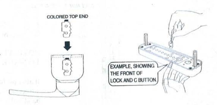
its is very important to replace the code tumblers in the correct way. the colored top end must always face upwards.
the side of the tumbler that has the raised notches must face toward the top of the lock.
remember to keep the 'c' pressed in while removing and replacing the tumblers.
replace the plate carefully and now test your code before replacing it on the door.