LockeyUSA 2230 2435 Mechanical Lock Instructions Template 1
Open the original PDF document
View PDF

Lockey 2230 | 2435
Installation Instructions
2230 | 2230 DC | 2435
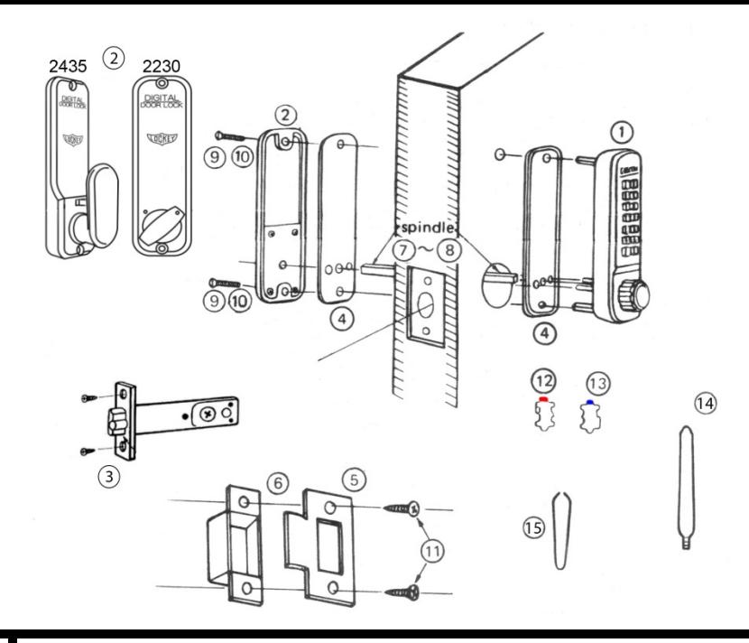
| No. | Part Name |
2230
2435 |
|---|---|---|
| 1 | Outside Body | 1 |
| 2 | Inside Body | 1 |
| 3 | Deadlatch (2 3/8" - 2 3/4") | 1 |
| 4 | Rubber Trim Plate | 2 |
| 5 | Strike Plate | 1 |
| 6 | Mortised Striker | 1 |
| 7 | Spindle 40-55mm. | 1 |
| 8 | Spindle 30-45 mm. | 1 |
| 9 | Machine Screw M4 x 50 mm. | 2 |
| 10 | Machine Screw M4 x 35 mm. | 2 |
| 11 | Wood Screws M4 | 4 |
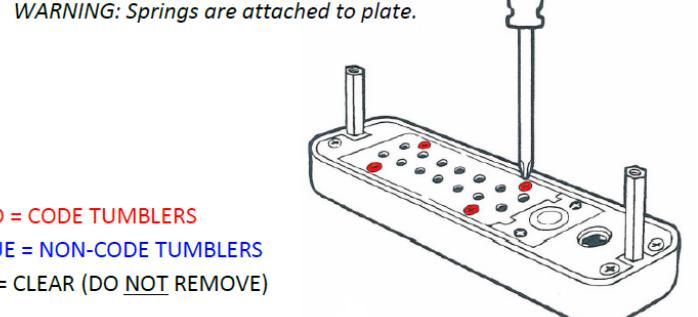
| 12 | Extra Code Tumblers (Red) | 1 |
| 13 | Extra Non-Code Tumblers (Blue) | 2 |
| 14 | Brass Support Pin | 1 |
| 15 | Tweezers | 1 |
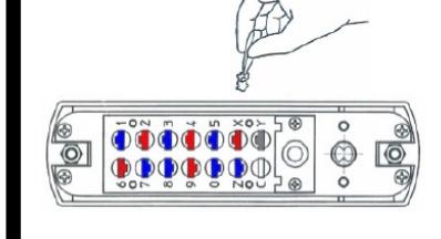
Step 1: Change User Code ( OPTIONAL )
If you wish to change your code, see instructions on reverse side.
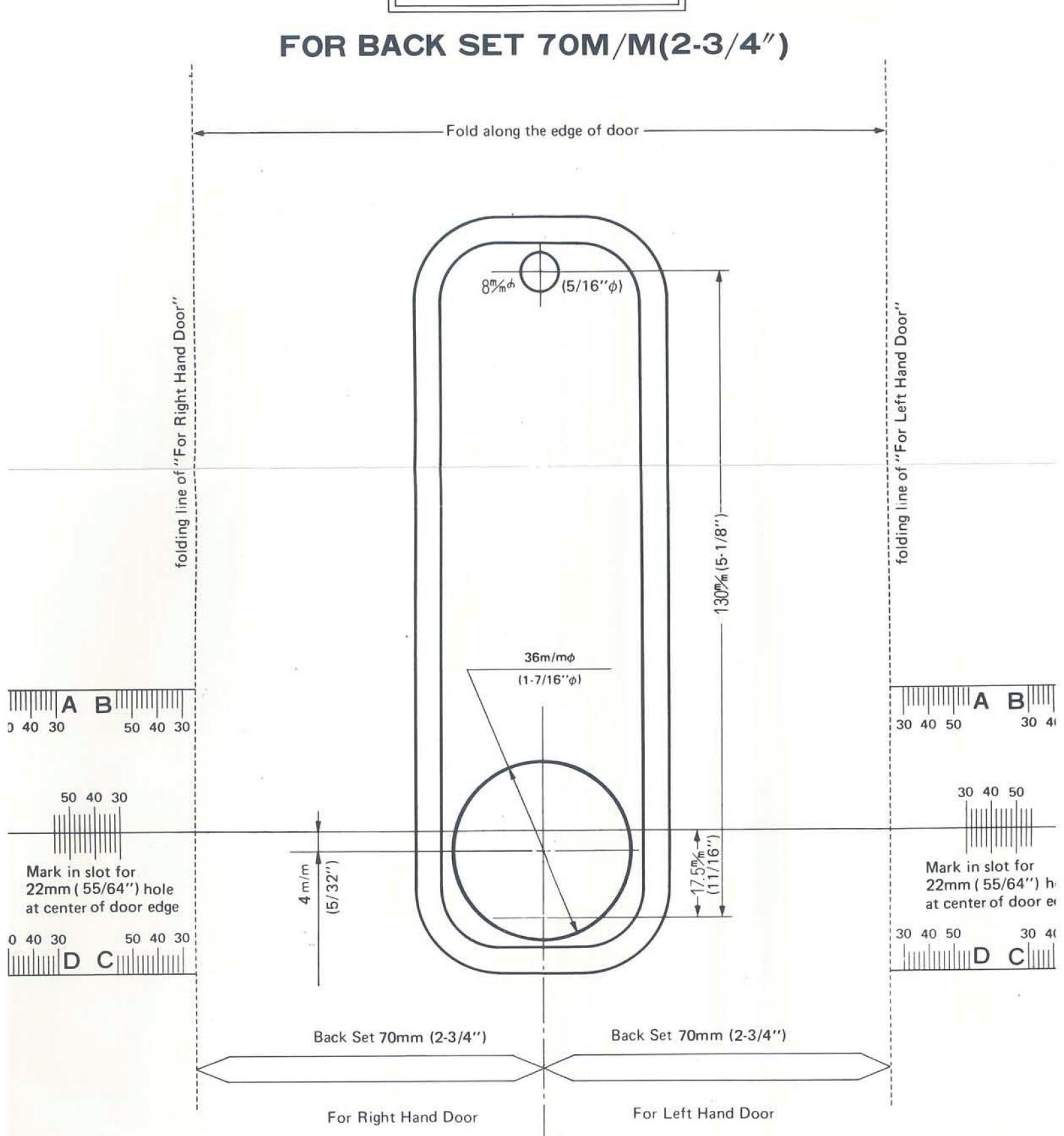
Step 2: Prep Door for Installation with Template
- 1. Place template (supplied) on door and fold along door's edge.
- 2. Mark holes for 2 3/8" or 2 3/4" backset.
- 3. Drill holes as instructed.
NOTE: For Pre-Prepped 2 1/8" doors, you only need to drill top hole.
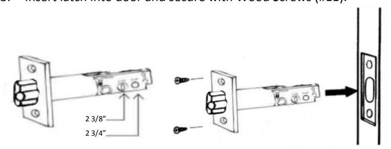
Step 3: Adjust Latch ( if necessary ) & Install
- 1. Adjustable latch (#3) is factory preset for a 2 3/8" backset.
- 2. For 2 3/4" backsets, slide the Cam assembly on the latch to 2 3/4".
- 3. Insert latch into door and secure with Wood Screws (#11).
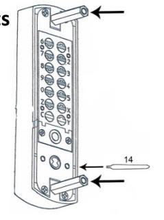
Step 4: Install Support Pin & Hex Bolts
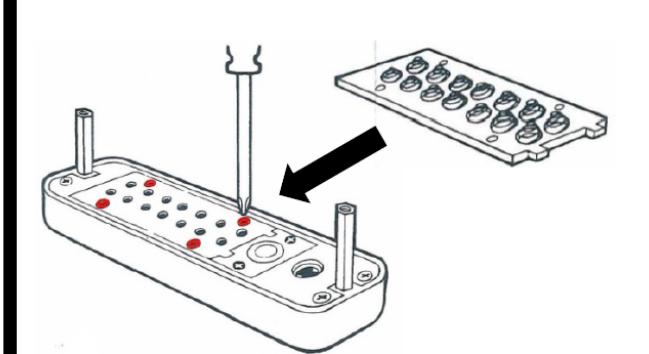
Install Brass Support Pin (#14) into either hole on Outside Body as shown in the figure to the Right.
Install/screw Hex Bolts into the top and bottom of the Outside Body as shown in the figure.
Step 5: Verify Correct Spindle Length
- 1. With latch (#3) installed, hold the Inside Body (#2) and Rubber Trim Plate (#4) to the door. Inside Body (#2) Inside Knob or Lever
- 2. Place Spindle (#7/8) through latch, into the Inside Body, as far as possible.
- 3. Spindle should extend from exterior of door 3/8" min. – 5/8" max.
- 4. If the 30-45 mm (#8) is too long, cut it to the correct length. IMPORTANT: If spindle extends less than 3/8" it may not engage the lock. If spindle extends more than 5/8", it will cause the lock to bind.
Step 6: Determine Knob Turn Direction ( to unlock )
The lock is preset to unlock when turned clockwise after combination is entered.
If desired, you can unlock the door with a counter-clockwise turn. Remove the two blue screws and move the pin to the opposite side as shown.
*2230 DC – Inside Body pin must on opposite side from Outside Body.
Step 7: Install the Lockey 2230/2435
- 1. Place the Rubber Trim Plate (#3) on the backside of the Outside Body (#1).
- 2. Place the Outside Body on the door. The hexagonal bolts should extend into the top and bottom holes.
- 3. The Support Pin (#14) on the Outside Body should fit into and extend through

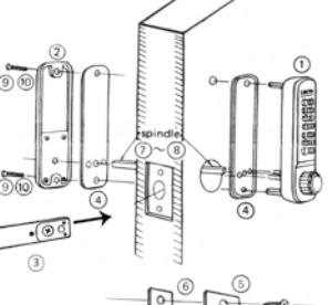
Door Edge
3/8" to 5/8"
Spindle (#5/6)
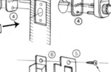
Step 7 cont: Install the Lockey 2230/2435
- 1. Insert the Spindle (#7/8) into the Outside Body (#1) ensuring it's in the proper angled position. *( SEE FIGURES BELOW )
- 2. Using a screwdriver, secure the lock to the door with the Screws (#9 or #10). Screw length is dependent on door thickness .
- 3. Test the operation of the Latch by turning the inside knob/lever.
- 4. Locate position where Latch strikes door frame and install Mortised Strike (#5) and Strike Plate (#6).
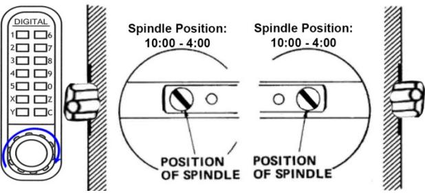
*IMPORTANT: SPINDLE POSITION/ANGLE
CLOCKWISE TURN TO UNLOCK WITH COMBINATION
The 2230/2435 is factory preset to unlock with a clockwise turn when the combination is entered. The Spindle MUST be placed through the latch, at a 10:00 – 4:00 angle as shown.
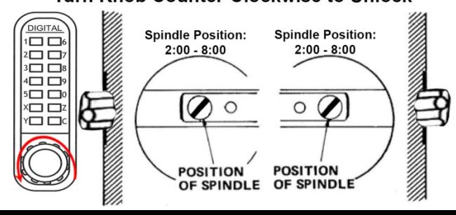
COUNTER-CLOCKWISE TURN TO UNLOCK WITH COMBINATION
If desired, the 2230/2435 can be unlocked with a counter-clockwise turn when the combination is entered. To unlock the 2230/2435 with a counter-clockwise turn, please refer to Step 6 to change the Handing Pin.
After changing the Handing Pin, the Spindle MUST be placed through the latch at a 2:00 – 8:00 angle as shown.

Template may not print at 100% accuracy. Please verify measurements before drilling holes/installing.
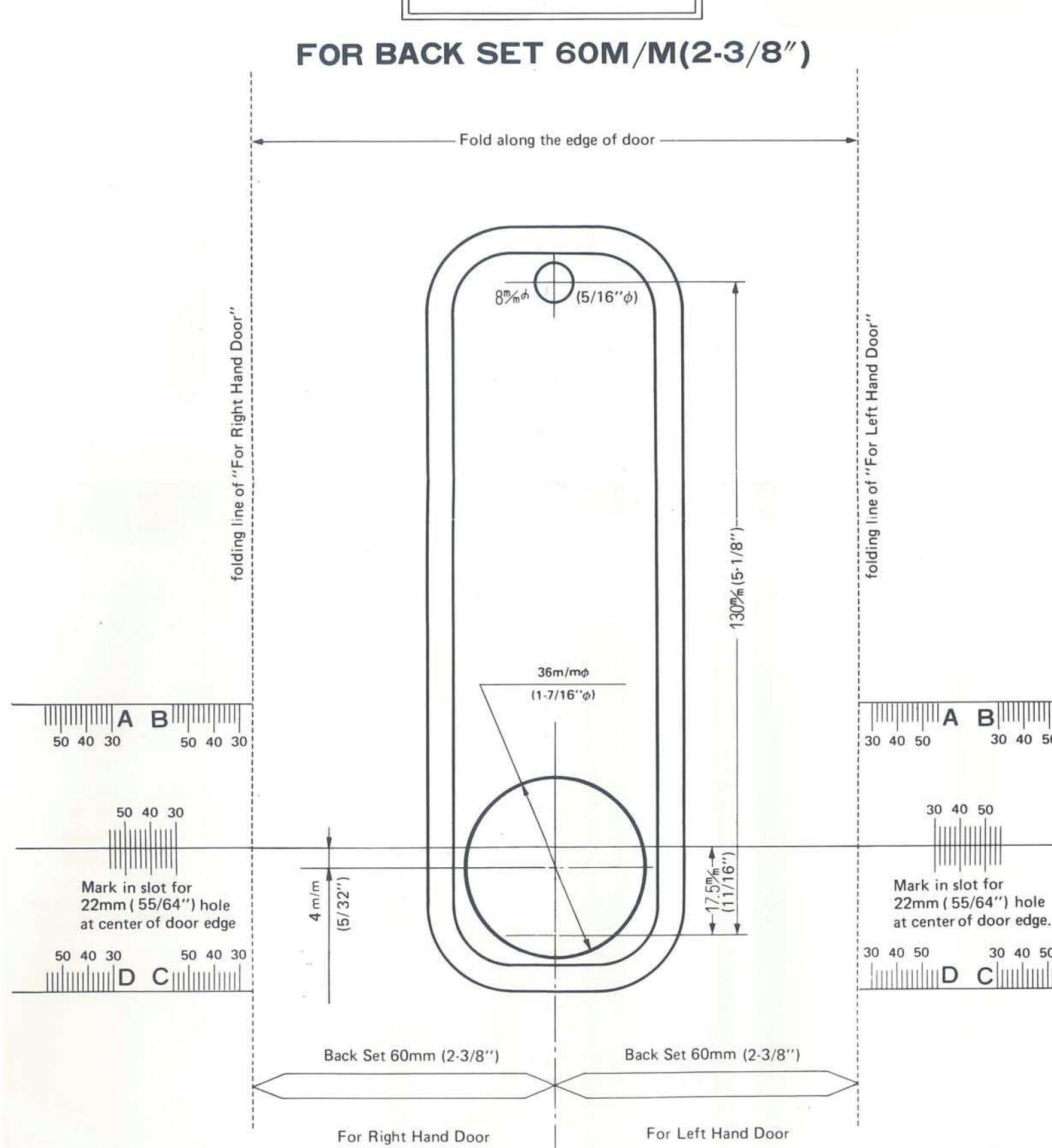
Template may not print at 100% accuracy. Please verify measurements before drilling holes/installing.