LockeyUSA 1150 1600 Mechanical Lock Instructions Reduced
Open the original PDF document
View PDF

1150 & 1600 INSTALLATION INSTRUCTIONS
| No. | Part Name | # Included |
|---|---|---|
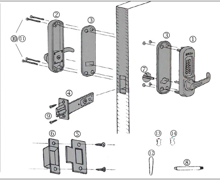
| 1 | Outside Body | 1 |
| 2 | Inside Body | 1 |
| 3 | Rubber Trim Plate | 2 |
| 4 | Adjustable Latch | 1 |
| 5 | Strike Plate | 1 |
| 6 | Mortised Striker | 1 |
| 7 | Spindle | 1 |
| 8 | Support Pin | 1 |
| 9 | Tapping Screws | 4 |
| 10 | M5 x 55m Screws | 4 |
| 11 | M5 x 45mm Screws | 4 |
| 12 | Tweezers | 1 |
| 13 | Red "Code" Tumblers | 1 |
| 14 | Blue "Non-Code" Tumblers | 2 |
- 1. Use the template provided and confirm the back set on the surface and the reverse side.
- 2. Decide the position for the lock and mark holes as instructed by template. Drill holes.
- 3. Insert the Adjustable Latch into the slot. Trace line around the Latch face and remove it.
- 4. Chisel until the Adjustable Latch face is flush with the surface of the door edge.
- 5. Fasten Adjustable Latch with the tapping screws. Important: Ensure the Adjustable Latch face is evenly fitted.
- 6. Break the spindle to the correct length according to the door thickness.
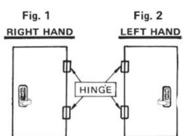
- 7. Determine Door Handing: Right-Hand Doors From exterior of door, hinges are on right-side (fig. 1). Left-Hand Doors – From exterior of door, hinges are on left-side (fig. 2). To change handing, remove screw on back of lever, then remove plate on lever. Remove two screws from lever handle, lift lever up and switch direction of handle. Replace screws and plate, fasten.
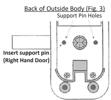
- 8. For right hand doors, install Support Pin in hole on left side of back of the Outside Body. For left hand doors, install Support Pin in hole on the right side of the back of the Outside Body.
- 9. Fit Rubber Trim Plate on the backside of the Outside Body, then hold Outside Body on door, with 4 hex bolts and Support Pin through the holes in door.
- 10. From inside of the door, insert Spindle through the hole in the Adjustable Latch & into hole on backside of Outside Body.
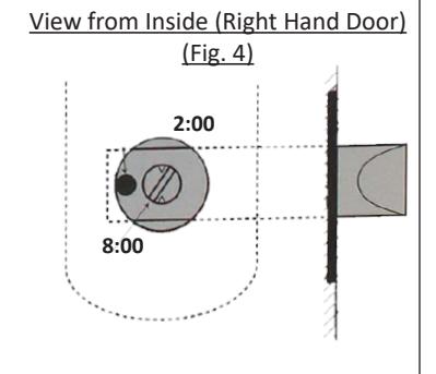
IMPORTANT: Right hand doors: Spindle must be at a 2:00/8:00 angle from the inside of the door (Fig. 4). Left hand doors: Spindle must be at 10:00/4:00 angle from the inside of the door.
- 11. Fit Rubber Trim Plate to the Inside Body and fit Inside Body over the Spindle, ensuring that Spindle angle remains correct.
- 12. Select Machine Screws based on door thickness and fasten them through the Inside Body.
IMPORTANT: Before closing the door, test the operation of the lock.
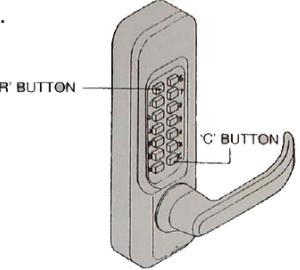
From Outside of Door:
- 1. Press "C" button, followed by your code.
- 2. Turn the handle.
- 3. Confirm that the latch head retracts smoothly.
From Inside of Door:
1. Turn the handle and ensure the latch retracts smoothly.
- 13. Close the door to determine where the Latch head touches to the face of the door jamb.
- 14. Chisel out the space for the Motised Striker and for the Strike Plate so that the Strike Plate is flush with the surface of the door jamb.
- 15. Fasten Mortised Striker and Strike Plate with screws.
PASSAGE FUNCTION
IMPORTANT: This lock is equipped with a Passage Function, allowing you to leave the door unlocked.
To enable passage function:
- 1. Push "C" button to clear.
- 2. Enter your code number, followed by the "R" button. Your lock is now in Passage.
To diable passage function:
1. Press the "R" button followed by the "C" button.
To permanently disable passage function:
- 1. Hold Outside Body in horizontal position.
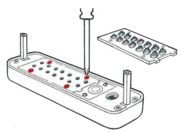
- 2. Remove the four red screws.
- 3. Carefully remove the plate, as there are many springs attached to it.
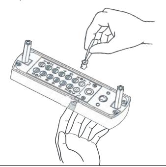
- 4. Press and hold the "C" button from underneath.
IMPORTANT: Remain holding the "C" button until the tumbler is removed.
- 5. Remove the "R" tumbler with the Tweezers provided.
- 6. Replace plate and replace four red screws.
HOW TO CHANGE CODE
Before changing code, read this information carefully. FAILURE TO FOLLOW INSTRUCTIONS CAN RESULT IN DAMAGE TO LOCK.
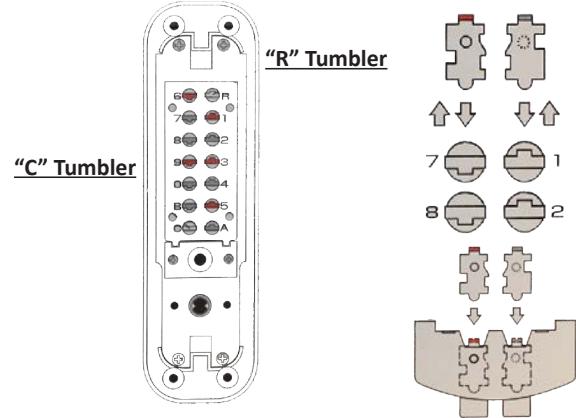
RED TUMBLERS = CODE TUMBLERS
BLUE TUMBLERS = NONCODE
"C" TUMBLER = CLEAR (cannot be removed)
"R" TUMBLER = PASSAGE FUNCTION (instructions above) (do NOT replace with any other tumbler)
1. Hold the Outside Body in horizontal position. Remove the four red screws. Carefully remove the plate.
2. Hold the "C" button from underneath from now until you have completed the code change.
FAILURE TO DO SO WILL DAMAGE THE LOCK.
While continuing to hold the "C" button, use tweezers to rearrange code/non-code tumblers to create desired code.
3. Code is made up of RED tumblers. Make sure the colored end is facing upwards. Example: If your desired code is 13569, red tumblers will be placed in numbers 13569 (shown below).
4. When completed changing your code, release the "C" button and replace the plate carefully.
5. Always test your new code before installing/re-installing the lock to the door. Remember to press "C" button before entering code.