Legault CS401 Dealy Operating Instructions
Open the original PDF document
View PDFMODEL CS401
PROGRAMMING THE TIME-DELAY
- Unless otherwise specified at the time of ordering, the time delay will be factory set at 10 minutes.
- The delay period can, at any time, easily be changed to one of the following settings (1-3-5-10-15 minutes).
- Be sure the lock has completed its cycle before attempting to change the time delay.
- Remove the timer cover by unscrewing the 4 cover retaining screws (7/64" allen key).
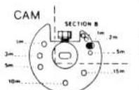
- To program the desired time delay remove the screw (7/64" allen key) from CAM (Figure 1, section A) and place it in the hole that corresponds to the required delay.)
- If a time delay of 15 minutes is required, simply remove this same screw and relocate it in the timer plate (Figure D - reverse side).
- · Replacing the cover in its original position:
- Make sure the key is removed from cylinder of the lock before replacing cover.
- Push in the lock latch.
- Align the dot on the cover with the dot on the lock.
- Replace cover using the 4 screws (7/64" allen key).
- Release lock latch.
- FOR TWO SWITCH LOCKS ONLY: Turn CAM clockwise to its maximum before replacing cover in original position.
- Test if the delay is accurate (±10 sec.). If not, ajust by winding (if too slow) or unwinding (if too fast) a 1/2 turn or a maximum of one full turn either way.
PROGRAMMING THE DURATION OF THE OPENING PERIOD:
- The time allowed for opening at the end of the delay is also limited. If the lock is not opened within the predetermined time limit, the opening sequence is automatically cancelled and the complete cycle must be repeated.
- Unless otherwise specified at time of ordering, the time allowed for opening after the initial time delay is 2 minutes. The delay period can at any time, easily be changed to one of the following settings (1-2-5 minutes).
- Remove the timer cover by unscrewing the 4 cover retaining screws (7/64" allen key).
- Turn CAM clockwise to its maximum and hold it in that position.
- To program the desired opening period, remove the screw (5/64" allen key) from CAM (Figure 1, Section B) and place it in the hole that corresponds to the time period required.
- If an opening time period of 5 minutes is required, simply remove this same screw and relocate it in the timer plate (Figure D - reverse side).
-
· Replacing the cover in its original position:
- Make sure key is removed from cylinder of the lock before replacing cover.
- Push in the lock latch.
- Align the dot on the cover with the dot on the lock.
- Replace cover using the 4 screws (7/64" allen key).
- Release lock latch.
- FOR TWO SWITCH LOCKS ONLY: Turn CAM clockwise to its maximum before replacing cover in original position.

CAM
GENERAL:
The lock is factory mounted for right hand opening. At the time of installation the lock may be mounted in any one of 4 opening positions: right hand, left hand, vertical up or vertical down.
INSTRUCTIONS FOR CHANGING THE OPERATING POSITION:
- Remove the timer cover by unscrewing the 4 cover retaining screws (7/64" allen key).
- Remove the TIMER PLATE, by unscrewing the 2 corner screws (1/16" allen key). Figure A.
- Remove the CAM by loosening the CAM retaining screw (7/64" allen key). Figure B.
- Remove the 3 screws (1/16" allen key) that hold the TIMER PLATE to the lock timer. Figure C.
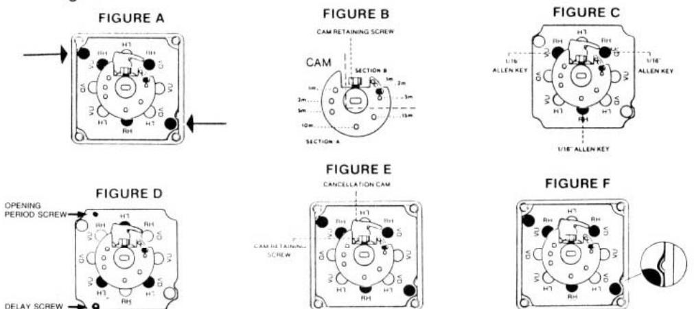
- TIMER PLATE legend: RH right hand; LH left hand; VU vertical up; VD vertical down.
- Using the legend above, align the 3 holes of the lock timer with those of the TIMER PLATE in the desired position. Ex.: left hand. Figure D.
- Align CAM (Figure B) on the timer shaft so that the CAM retaining screws (7/64" allen key) is in line with the cancellation CAM. Figure E.
- Tighten the CAM retaining screw (7/64" allen key).
- Replace the TIMER PLATE in the cover (align the notch of the TIMER PLATE with the protuding stud of the cover), and tighten the 2 corner screws (1/16" allen key). Figure F.
-
· Replace the cover in its original position:
- Make sure key is removed from the cylinder of the lock before replacing the cover.
- Push in the lock latch.
- Align the dot on the cover with the dot on the lock.
- Replace cover using the 4 screws (7/64" allen key).
- Release lock latch.
- FOR TWO SWITCH LOCKS ONLY: Turn CAM clockwise to its maximum, before replacing cover in original position.
Note: This entire procedure should be completed as quickly as possible to avoid unwinding the movement.
If for any reason the timer has run down partly or completely, rewind clockwise up to a positive stop (do not force). Then, unwind 3 full turns. Reposition the cam and replace cover onto the lock in order to test if the delay is correct. If not, ajust by winding (if to slow) or unwinding (if to fast) a 1/2 turn or maximum one full turn either way.