Latch_Guard_Installation_Instructions_Inswing
Open the original PDF document
View PDFInswing Latch Guard Installation Instructions – LGI
Important Warranty Information:
The following actions will void any warranty, express or implied:
- Failure to install the Latch Guard properly, with supplied fasteners.
- Unauthorized field modifications, including alteration of the original finish or painting
NOTE: Latch Guard can be trimmed around frame and door hardware, but Latch Guard must remain as a single piece and sit flat on face of frame and door – do NOT cut into sections.
1: Preparation
- A. With the door closed, place both portions of Latch Guard on soffit of frame and closed door as shown (Fig. 1). To help with centering, it is recommended to place the pink foam material, supplied as part of the packaging material, over the male portion near top and bottom. Press the female section over the male, wedging the foam material between both parts to hold the sections in position for mounting, making sure to also center this section vertically and NOT get the foam trapped between the Latch Guard and door. Using the correct vertical spacing, and while making sure that this piece is flush with the frame and not overhanging far enough to interfere with the door closing, fasten firmly in place using the supplied self-drilling panhead hardware in the holes provided. You may also mark the fastener holes in the frame and door first with a pencil or punch if desired.
- B. Using the pre-drilled holes in the Latch Guard, drill the six 3/8" diameter holes through the door. You may also mark the hole locations on the door, remove the female Latch Guard and drill the six 3/8" diameter holes through the door with the female section of the Latch Guard removed if preferred and reinstall.
- C. Drill additional holes near the middle of the Latch Guard and attach using the last of the self-drilling fasteners provided, making sure to space the holes equally and concentrate near the strike location. (6 holes have been provided, we suggest a minimum of 8, spacing additional holes evenly around existing hardware for frame AND door.)
- D. With the door open and foam removed, push the barrel nuts through the extrusion and door at each hole location and tighten each of the shoulder bolts from the other side of the door. Close the door and check fit and function. Now drill the final three holes and install the remaining barrel nuts and shoulder bolts.
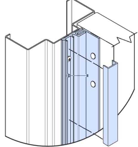
- E. With the door still open, starting at the top of the Latch guard, and using a plastic mallet or hammer and a block of wood, press the frame cover on firmly, working from top to bottom. (Fig. 2)
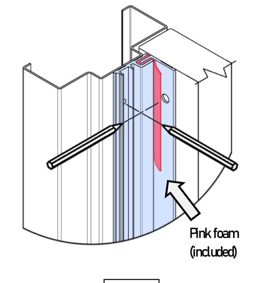
Fig. 1
Supplied Hardware:
Self-Drilling Panhead Barrel Nut Shoulder Bolt
Fig. 2