La Gard Electronic Lock Installation Instructions
Open the original PDF document
View PDF
ELECTRONIC LOCK INSTALLATION INSTRUCTIONS
TABLE OF CONTENTS
| ENERAL INFORMATION | 1 |
|---|---|
| OCK MOUNTING TEMPLATE | 2 |
| WING BOLT | 3 |
| EAD/SPRING BOLT | 1_5 |
| LAD/SFRING BOLI |
|
| EDUNDANT MECHANICAL | 6 |
ELEC TRONIC LOCKS
INSTALLATION INSTRUCTIONS
GENERAL INFORMATION
In order to maintain the highest quality standards and ensure a problem-free application, please read this guide thoroughly before mounting the unit. The installation instructions are the basis for Security Agency Approvals. The installation must be done in accordance to these instructions in order to maintain the labeled approval level.
SAFEGUARDS FOR MOUNTING
- 1. Once an electronic lock has been mounted, no more welding can be done on the safe.
- 2. Keep metal dust, filings, etc. away from the lock.
- 3. Never remove lock cover on a Dead Bolt, Spring Bolt or Swing Bolt lock as this voids warranty policy.
- 4. Never oil, grease, lubricate or paint the lock.
- 5. Keep cables away from sharp edges and moving parts.
- 6. Never carry keypads or locks by the cable.
- 7. Use 9-Volt ALKALINE batteries only. The use of a high quality, name brand battery (Energizer® or Duracell®) is recommended.
BASIC TOOLS AND MATERIALS REQUIRED:
- Medium Phillips head screwdriver (#2) (recommend magnetized tip)
- Small flat file or deburring stone
- Tape measure or ruler
- ESD wrist band
For dead bolt, spring bolt, or redundant mechanical installation:
- Fine pitch hacksaw (32 teeth/inch)
- Small vise grip (Recommended)
WARNING: LA GARD locks are protected from 25,000 V Electrostatic Discharge (ESD) damage when correctly installed. Follow these precautions to avoid ESD damage when installing the lock:
- Handle the keypad assembly by the outer edge only.
- Use an ESD wrist band grounded to the lock or container during installation.
PREPARATION FOR NEW INSTALLATION: (IF REQUIRED)
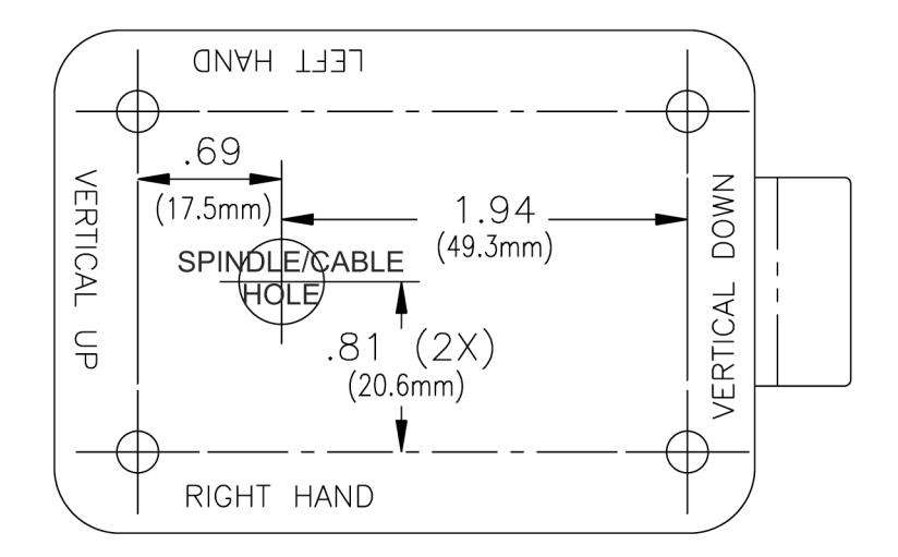
- 1. Use the template to establish the exact locations (relative to the spindle hole) of the mounting holes for the Entry Device and the lock assembly. Be sure to consider the cable length from the entry device to the lock.
- 2. The spindle hole diameter can be a minimum of .406" (10.3mm) to a maximum of .438" (11.1mm). The .406" (10.3mm) diameter is recommended. Spindle hole must be deburred.
- 3. The lock mounting screws (1/4-20 or M6) require tapped holes; the recommend depth is .375" (9.5 mm), but a minimum depth of .250" (6.4 mm) is required.
- 4. When mounting the lock unit (i.e., integrating it in a boltwork), make sure that the lock bolt has clearance to freely move to its end positions and that the shifting force works only in the axial direction (direction of movement). Lateral forces should not be exerted on the lock.
- 5. If other parts of the boltwork are to be connected to the lock unit (e.g., for activating a blocking device), corresponding adapters can be fixed with screws (#10-32 or M4) to the front of the lock bolt (tightening torque for 15mm screwing depth: 200Ncm maximum).
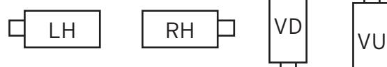
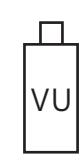
LA GARD locks can be mounted in four (4) orientation positions.
- Left Handed
- Right Handed
- Vertical Down
- Vertical Up

SWING BOLT LOCK
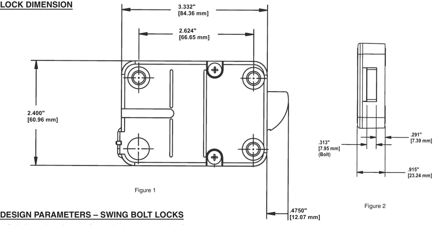
- 1.Bolt dimensions (nominal): .313 inches x .900 inches/7.95 x 22.8 mm
- 2.Bolt movement (nominal): .475 inches/12.1 mm
- 3.Bolt extension: .475 inches/12.1 mm
- 4. Maximum load movable by the bolt: None
NOTE: LA GARD swing bolt locks will not open if force is applied to the end or side of the bolt.
- 5. Maximum load against bolt when thrown (all directions): 1kN (224.8 lbs.)
- 6. The lock can be fitted to safes or vault doors of any material.
NOTE: In order to maintain VdS Class 2/EN 1300 Class B lock approval levels in a container where multiple locks are required, special considerations must be observed. The Swingbolt lock must be the first one secured by the boltworks. Check the locked status of the container with the handle of the boltworks.
As is the case with all mechanical and electronic locking devices, the container and boltworks must be designed to protect the lock.
INSTALLATION - SWING BOLT LOCKS
- 1. Locate, drill and tap holes to mount the Lock Assembly to the inside of the safe door using the installation template provided.
- 2. Install Entry Device according to LA GARD instructions (p/n 762.128).
- 3.Ensure that the Entry Device cable is running through the channel at the back of the lock; while ensuring the lock is flush against the mounting surface.
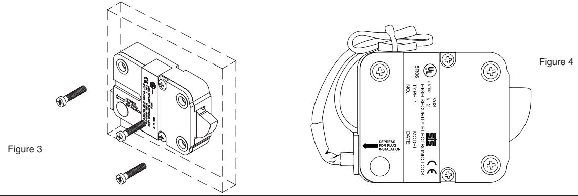
- 4. Mount the lock with the three US 1/4-20 (Metric M6X1) screws. The recommended torque for mounting screws on the Swing bolt lock is 30 in./lbs. (3.4 N•m). (Figure 3.)
- 5. Secure any cables with wire tie, making sure to keep out of the way of all moving parts (Figure 4).
- 6. Connect the cable coming from the Entry Device directly into the connector port marked ENT on the lock (Figure 4).
BOLTWORKS PRECAUTIONS - SWING BOLT LOCKS
The blocking part "A" (Figure 5) of the boltwork should exert force across the entire width of the lock bolt while opening. But, in the locked position the boltwork MUST NOT place pressure on the lock bolt. This could cause the lock to jam.
NOTE: In case of boltwork construction where two blocking parts are moving opposite one another, the one facing the round side of the lock bolt "B" should be cut off to avoid jamming of lock bolt (Figure 5).
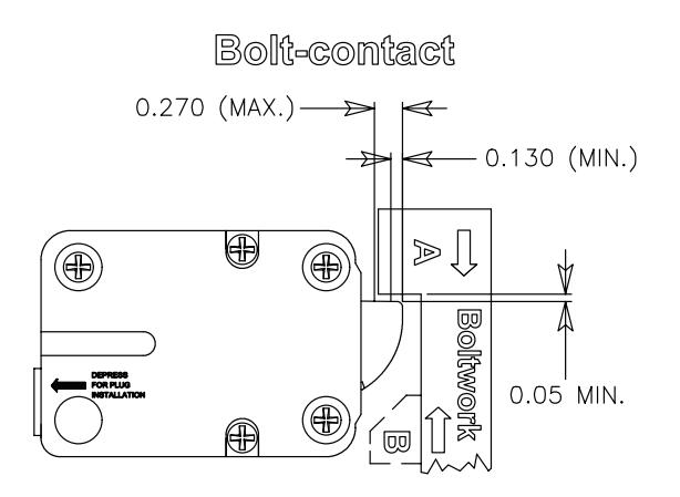
Figure 5
DEAD BOLT, SPRING BOLT, REDUNDANT MECHANICAL
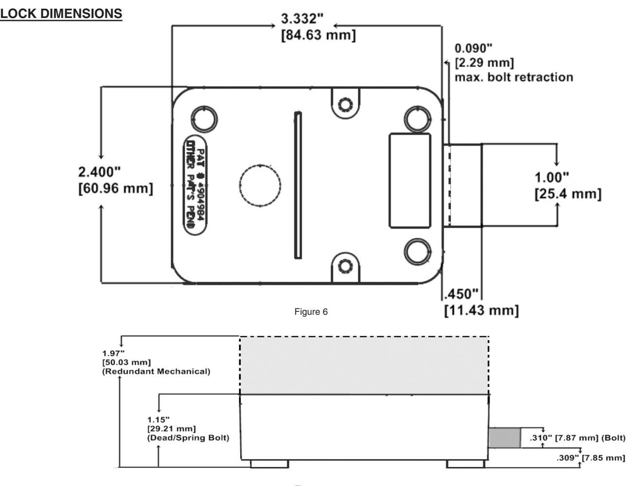
Figure 7
DESIGN PARAMETERS – DEAD BOLT, SPRING BOLT AND REDUNDANT MECHANICAL LOCKS
- 1.Bolt dimensions (nominal): .310 inches x 1.000 inches/8 x 25.4 mm
- 2.Bolt movement (nominal): .340 inches/8.6 mm
- 3.Bolt extension: .450 inches/11.4 mm
- 4. Maximum load movable by the bolt: 5 lbs. (22N)
NOTE: LA GARD dead bolt locks may not open if more than 5 lbs. (22N) of force is applied to the end or side of the bolt.
- 5. Maximum load against bolt when thrown (all directions): 224.8 lbs. (1kN)
- 6. The lock can be fitted to safes or vault doors of any material.
NOTE: As is the case with all mechanical and electronic locking devices, the container and boltworks must be designed to protect the lock.
INSTALLATION - DEAD BOLT AND SPRING BOLT
- 1. Locate, drill and tap holes to mount the Lock Assembly to the inside of the safe door using the installation template provided.
- 2. Install entry device according to LA GARD instructions (p/n 762.128); the spindle should extend .350" (9mm) from the mounting surface (Figure 8).
- 3. Install the lock (with the bolt extended) onto the spindle, placing it flush to the mounting surface.
- 4. Mount the lock with the three US 1/4-20 (Metric M6X1) screws. The recommended torque for mounting screws on the Swing bolt lock is 30 in./lbs. (3.4 N•m) (Figure 9).
- 5. Secure any cables with wire tie, making sure to keep out of the way of all moving parts (Figure 10).
- 6. Connect the cable coming from the Entry Device directly into the connector port marked ENT on the lock (Figure 11).
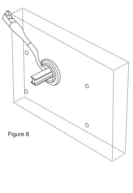
Figure 10
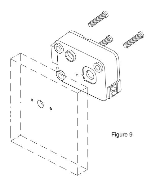
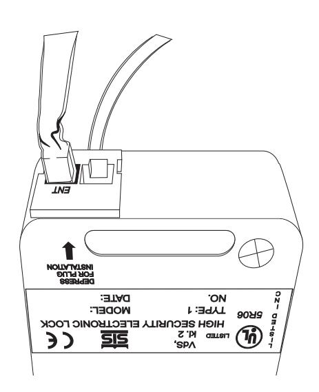
Figure 11
INSTALLATION - REDUNDANT MECHANICAL
- 1. Locate, drill and tap holes to mount the Lock Assembly to the inside of the safe door using the installation template provided.
- 2. Mount the lock with the three US 1/4-20 screws. The recommended torque for mounting screws on the Swing bolt lock is 30 in./lbs. (3.4 N•m) (Figure 12).
NOTE: It is not necessary to remove the mounting screws during the installation of the dial assembly or when servicing the lock. Ensure the lock assembly is properly aligned with the spindle through hole in the safe door.
3. Remove the two cover screws from the back cover of the lock assembly, and remove the lock back cover (Figure 12).
WARNING: Ensure that you are properly grounded to protect the system card from Electrostatic Discharge (ESD) damage
- 4. Carefully unplug the solenoid connector from the system card. (If applicable, unplug the bolt switch connector from the system card.) (Figure 12.)
- 5. Remove the mounting screw from the system card, and gently lift the system card out of the case (Figure 12).
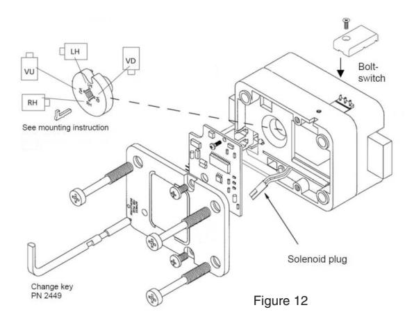
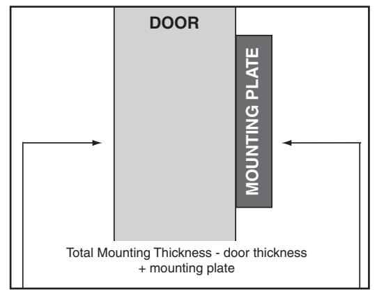
Figure 13
INSTALLATION - DIAL ASSEMBLY
In order to use a Redundant Mechanical lock, a method of retracting the bolt is required. Use of the VISIONGARD Dial (P/N 2085) is recommended (Figure 4). An entire range of LA GARD dials is available for alternate dial options.
WARNING: The lock bolt MUST remain in the retracted position throughout the installation procedure. To ensure this keep one finger over the bolt while installing the dial spindle into the lock cam.
- 1. Measure total mounting thickness (door thickness + mounting plate). (Figure 13.)
- 2. Cut the spindle to a length of 1.125" (28.6mm) plus the total mounting thickness.
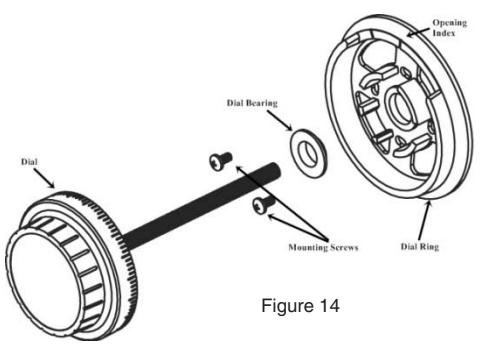
- 3. Mount the dial ring centered on the through hole, and attach to the safe door using the two mounting screws supplied with the dial assembly. The opening index reference mark must be in the twelve o'clock position (Figure 14).
- 4. Place the dial bearing onto the dial ring.
- 5. Insert the spindle through the hole in the door.
- 6. With the bolt retracted, carefully thread (clockwise) the spindle into the drive cam until tight.
- 7. Next, rotate (counterclockwise) at least 1/2 turn until the groove in the spindle is aligned with the correct spline position.
- 8. Insert the spline key fully into the cam from the back of the lock assembly by tapping it into place.
IMPORTANT NOTE: Ensure the spline key is seated against the spindle.
- 9. Reinstall the system card.
- 10. Reconnect the solenoid (and bolt switch if applicable.)
- 11. Reinstall the back cover.
NOTE: Ensure the cable is secure and away from any moving parts.
12. Plug the cable from entry device into the connector marked ENT. Ensure the cable is secure and away from any moving parts.