LR6000 Hospital Latch Installation Template
Open the original PDF document
View PDF
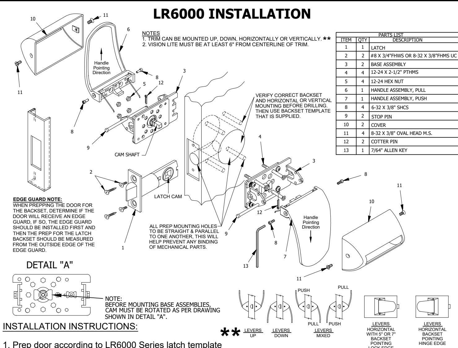
1. Prep door according to LR6000 Series latch template
2. Install latch using either #8 wood screws or 8-32 machine screws (Item 2).
- 3. Check (1) base assembly (Item 3) to ensure the cam is the position shown in Detail A (See above) Place the base assembly on the push side of the door by inserting the cam shaft into the latch cam as detailed above.
- 4. Check the other base assembly (Item 3) and ensure the cam is the position shown in Detail A (See above). Place base assembly on the pull side of door by engaging the shaft into the latch cam as detailed above. Fasten both base assemblies together with (4) 12-24 screws (Item 4) and (4) 12-24 hex nuts (Item 5). Test that cams rotate freely on both sides of the door after tightening the screws.
- 5. Install the push handle assembly (Item 7) to the base assembly installed on push side of door using (2) socket head cap screws (Item 8). Insert (1) stop pin (Item 9) through the push base assembly on the the same side of the direction the push handle is pointing. Test push handle for proper operation to be sure stop pin was installed in appropriate base assembly hole.
- 6. Repeat Step #5 on the pull side of the door for the pull handle assembly (Item 6). Insert (1) stop pin (Item 9) through the pull base assembly on the opposite side of the direction the pull handle assembly is pointing. Test pull handle for proper operaton to be sure stop pin was installed in appropriate base assembly hole.
- 7. Place covers (Item 10) over handles and fasten each cover with (2) 8-32 screws (Item 11).
PATENT PENDING

www.abhmfg.com E-mail: abhinfo@abhmfg.com Architectural Builders Hardware Mfg., Inc. 1222 Ardmore Ave., Itasca, IL 60143 630,875,9900; FAX 800,9FAXABH (932,9224)
LR6000-1-04.DWG
R6000 PAGE 1 OF 3
© 2022 ABH Mfg., Inc. printed in USA
REVISED 03-02-22
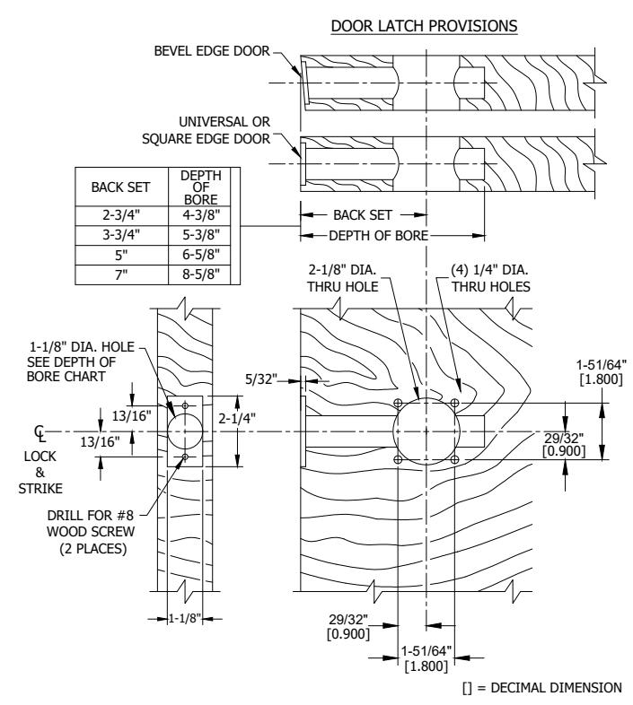
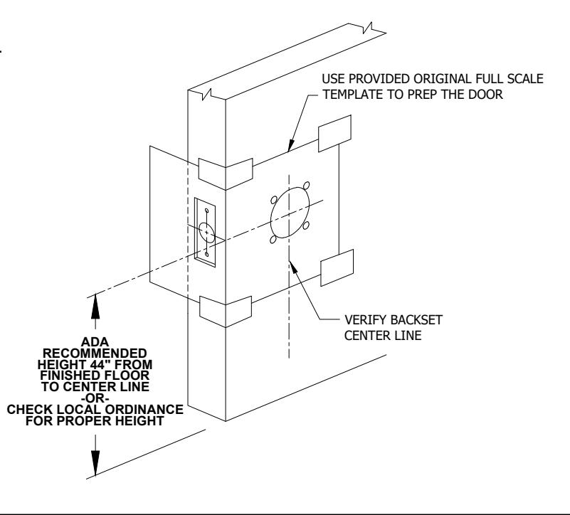
LR6000 PUSH/PULL LATCH - DOOR PREP
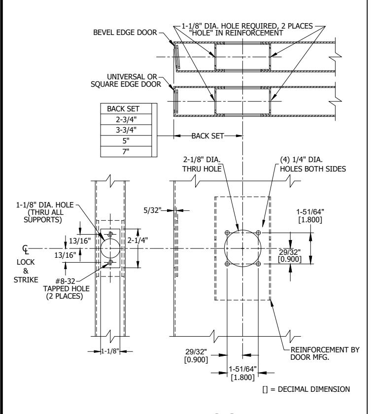
METAL DOOR
WOOD DOOR

1. BACKSET DIMENSION FROM LOW EDGE OF BEVEL.
2. CENTER PUNCH ALL HOLES.
3. DRILL HOLES (FOR HOLLOW METAL DOORS, DO NOT DRILL THRU. CENTER PUNCH & DRILL HOLES FROM BOTH SIDES OF DOOR).
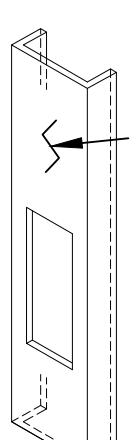
EDGE GUARD NOTE: WHEN PREPING THE DOOR FOR THE BACKSET, DETERMINE IF THE DOOR WILL RECEIVE AN EDGE GUARD, IF SO, THE EDGE GUARD SHOULD BE INSTALLED FIRST AND THEN THE PREP FOR THE LATCH BACKSET SHOULD BE MEASURED FROM THE OUTSIDE EDGE OF THE EDGE GUARD.

www.abhmfg.com E-mail: abhinfo@abhmfg.com Architectural Builders Hardware Mfg., Inc. 1222 Ardmore Ave., Itasca, IL 60143 630.875.9900; FAX 800.9FAXABH (932.9224)
LR6000-2-04.DWG
LR6000 PAGE 2 OF 3
© 2022 ABH Mfg., Inc. printed in USA
REVISED 03-02-22
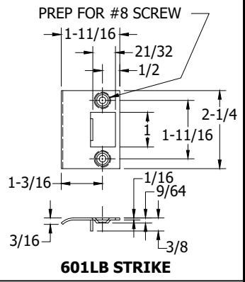
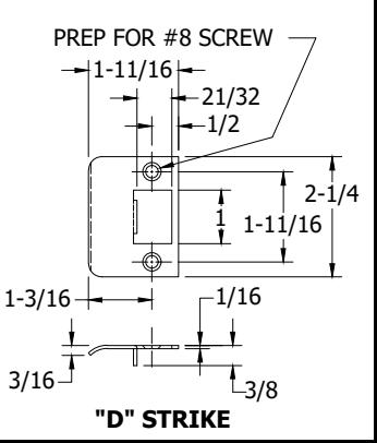
LR6000 PUSH/PULL LATCH - FRAME PREP REINFORCEMENT BY FRAME MEG G LOCK & STRIKE HALF DOOR THICKNESS DOOR STOP (MEASURED FROM STOP OR 1-1/4" SILENCER WHEN USED) +1/64-0 MORTAR #12-24 TAPPED HOLE GUARD (2 PLACES) 3-3/8" (MIN) 3-3/8' LOCK -0 2-1/16 STRIKE 1-1/16' 1" (MIN) METAL FRAME (ASA STRIKE SHOWN FOR EXAMPLE)
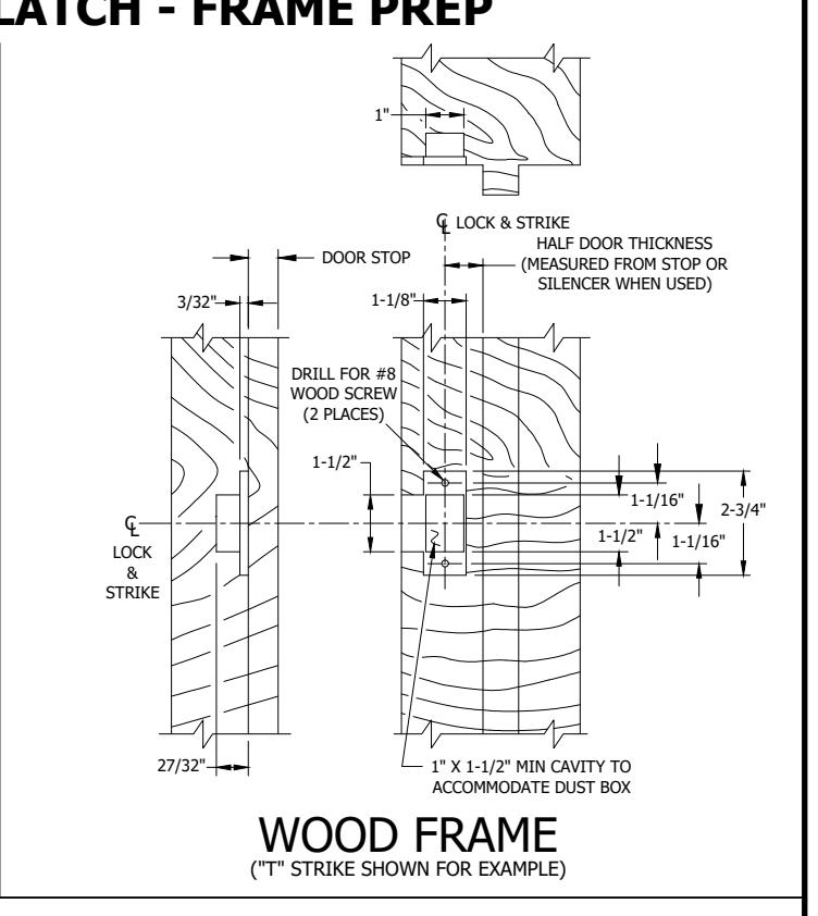
FRAME PREP
- 1. Mark centerline of latch bolt on frame.
- 2. Center strike and mark screw positions.
- 3. Mortise to required strike and box depth.
- 4. All dimensions in inches.
LR6000-3-04.DWG

www.abhmfg.com
E-mail: abhinfo@abhmfg.com Architectural Builders Hardware Mfg., Inc. 1222 Ardmore Ave., Itasca, IL 60143 630.875.9900; FAX 800.9FAXABH (932.9224)
© 2022 ABH Mfg., Inc. printed in USA
PAGE 3 OF 3 REVISED 03-02-22