LPM190 Series Insert Instructions
Open the original PDF document
View PDF


LPM 190 SERIES


KIT INCLUDES
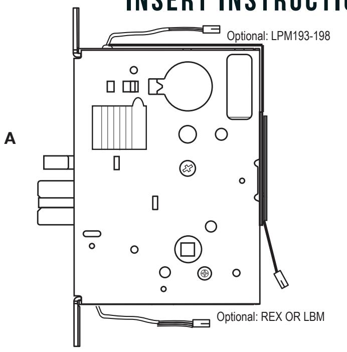
- A. 1-I PM19X SFRIFS MORTISF LOCK
- B. 1-51056 2 POSITION 48" WIRE HARNESS
- C. 1-50436 2 POSITION 8' WIRE HARNESS (LPM193-98)*
TOOLS REQUIRED
- CHISEL/WOOD RASP FILE
- 1" SPADE BIT
SPECIFICATIONS
LATCH RETRACTION
- INPUT VOLTAGE: 24VDC +/- 10%
- AVERAGE LATCH RETRACTION CURRENT: 1A
- AVERAGE HOLDING CURRENT: 300 MA
- WIRE GAUGE: MINIMUM 18 GAUGE
- DIRECT WIRE RUN NO RELAYS OR ACCESS CONTROL UNITS IN-BETWEEN POWER SUPPLY & LOCK
LEVER CONTROL
- INPUT VOLTAGE: SPECIFY 24VDC OR 12VDC +/- 10%
- CURRENT 24V = 350MA
- CURRENT 12V = 700MA
OPTIONAL BUILT-IN SWITCHES
SPDT - RATED 5A @24V
-
REX GREEN= COMMON (C)
- BLUE = NORMALLY OPEN (NO)
- GREY = NORMALLY CLOSED (NC)
-
GREEN/BLK=COMMON(C) LBM •
- BLUE / BLK = NORMALLY OPEN (NO)
- GREY/BLK = NORMALLY CLOSED (NC)
RECOMMENDED POWER SUPPLIES: USE A POWER LIMITED CLASS
I n s ta l l at i o n I n s t r u c t i o n s

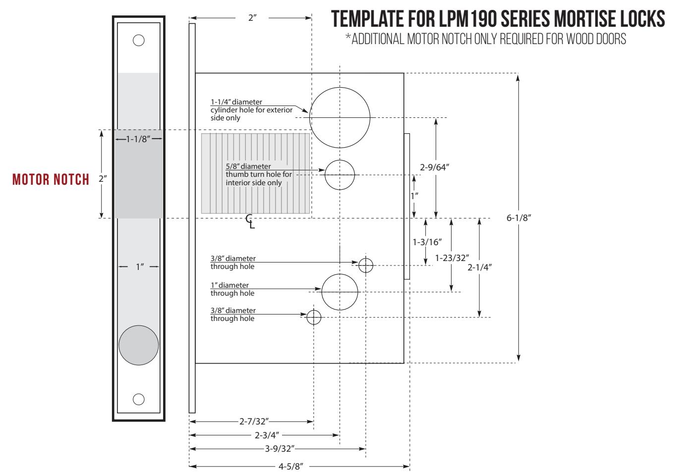
- 1. The door must be prepared according to our LPM190 template and a 3/8" wire raceway. Be sure that the mortise pocket and the raceway are clear of debris prior to installation.
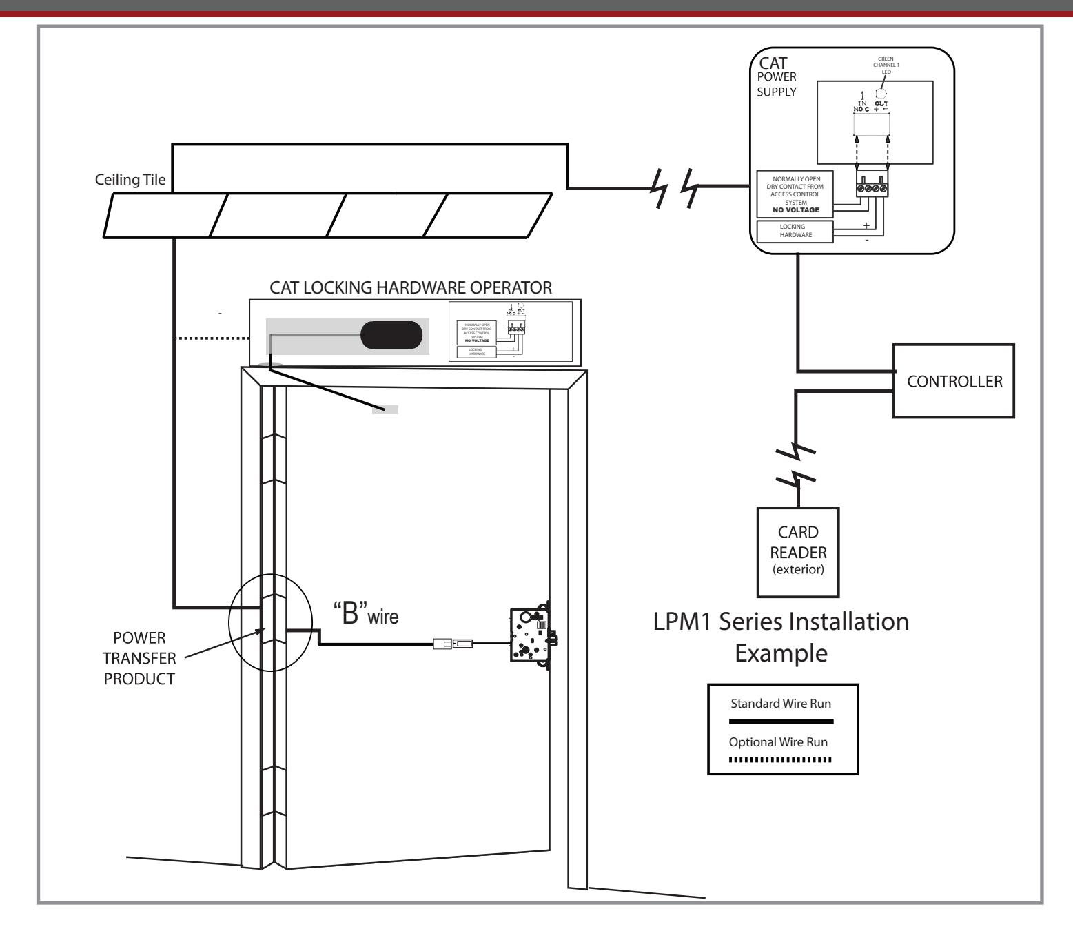
- 2. Install the "B" wire through the wire raceway leaving enough slack to "quick connect" to the mortise chassis.
- 3. Hardware wire "B" directly to electric hinge (CAT ETH4WH or 420W) or other transfer device, 18ga wire min.
- 4. Connect the wire run coming from the 26.5VDC power supply (not included - PS220 or PS210) into power transfer. The power supply may be up to 300 feet away (see power supply wiring instructions). Note: these wires are not polarity sensitive.
INSTALLATION INSTRUCTIONS

FOR LEVER CONTROL SOLENOID ON LPM MODELS 193-198 ONLY
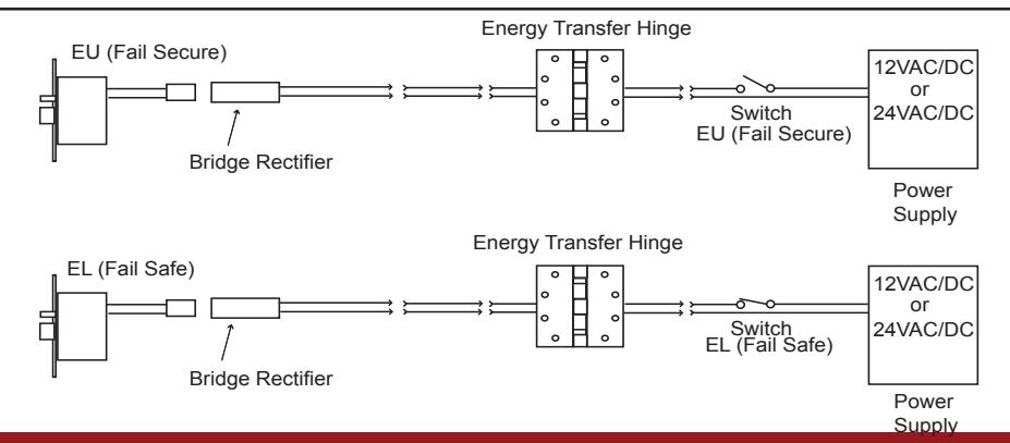
1 The door must be machined with a 3/8" wire raceway, mortise lock pocket & prepped for a energy transfer hinge. Make sure the mortise pocket is free of debris.
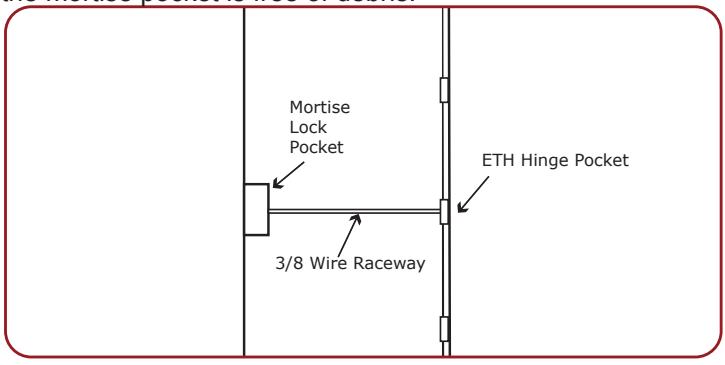
2. Run the wires from the ETH hinge through the 3/8" raceway starting at the ETH hinge & exiting into the mortise pocket.
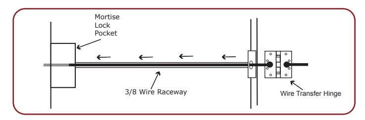
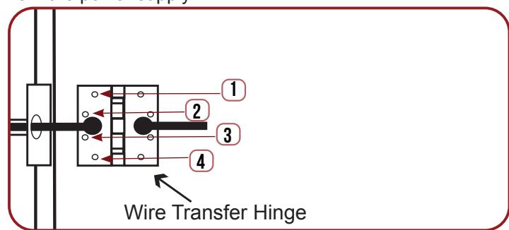
3 Screw the ETH hinge to the door. At this time <u>DO NOT</u> connect the hinge wires on the jamb side to the wires coming from the power supply.
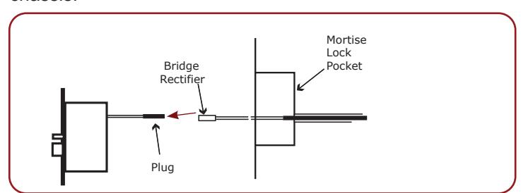
4. Connect the wires exiting the mortise pocket to the Bridge Rectifier (included).
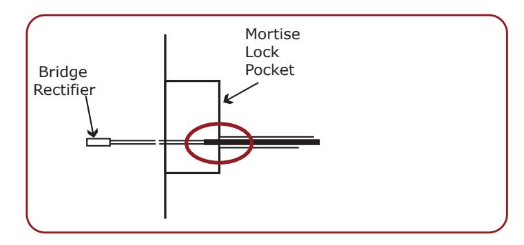
Connect the Bridge Rectifier to the plug exiting the mortise chassis.
6. Carefully slip the connected mortise lock chassis into the mortise pocket paying close attention not to pinch any wires.
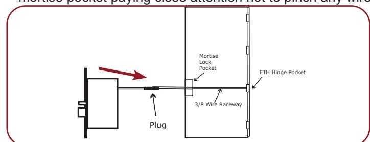
7 Mount the chassis per manufacturer's instructions.
8. Connect the wires from the power supply at the ETH hinge on the jamb side. Connect the hinge to the jamb.
INSTALLATION INSTRUCTIONS

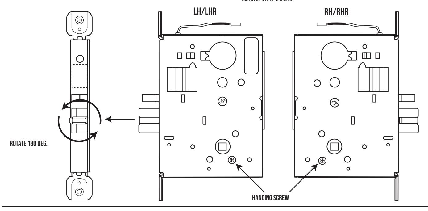
HOW TO CHANGE HANDING
- 1 LOCATE THE HANDING SCREW. THIS SCREW IS USED TO HAND THE HANDLES. THE LOCKING SIDE IS OPPOSITE THE SCREW.
- 2. TO HAND THE LATCHBOLT, REMOVE THE FACEPLATE. PULL THE LATCHBOLT OUT OF THE CHASSIS AND ROTATE, THEN RELEASE. THE LATCHBOLT IS SPRING LOADED AND WILL RETURN ON IT'S OWN.