LPM1-Series-Insert-Instructions-1
Open the original PDF document
View PDFLPM1 Series

INSTALLATION INSTRUCTIONS
The Latch Pullback Mortise Lock retracts the latch for push/pull operation. These instructions cover all series from LPM110-LPM188.
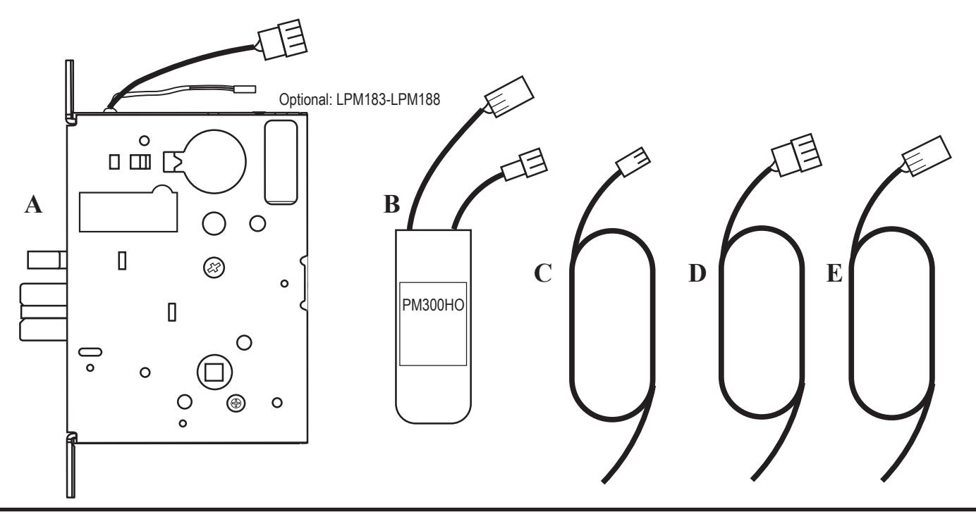
LPM Includes
- A. 1- LPM1 Series Mortise Lock
- B. 1- PM300HO
- C. 1- 96" 18ga w/ Female 2-prong lead (2 position connector)
- D. 1- 72" 18ga w/ Male 2-prong lead (3 position connector)
- E. 1- 72" 18ga w/ Female 2-prong lead (3 position connector
SPECIFICATIONS
Latch retraction
- Input Voltage: 24VDC +/- 10%
- Average Latch Retraction Current: 7A
- Average Holding Current: 260mA
- Wire Gauge: Minimum 18 gauge
- Wire Run: 300' MAX
PM300HO
- Input Wires to PM: Non-polarized Black (+/-)
- Output Wires for PM: Yellow = Pull Coil, Green = Common
Lever Control
- Input Voltage: 24VDC +/- 10% or 12VDC +/- 10% (Must specify)
- Current: 24V = 350mA
- Current: 12V = 700mA
Switches
-
Green = Common (C) REX
- Blue = Normally Open (NO)
- Gray = Normally Closed (NC)
-
Green/Black = Common (C) LBM
- Blue/Black = Normally Open (NO)
- Gray/Black = Normally Closed (NC)
-
White = Common (C) DPS
- Blue = Normally Open (NO)
- Black = Normally Closed (NC)
ReQUIRED Power Supplies: PS210,PS1, PS220/220B,& PS440B power supplies
All Command Access LPM1 series mortise locks have been thoroughly cycle tested with Command Access power supplies at our factory & are REQUIRED for proper operation. Using a non-command access power supply will void our warranty.
I n s ta l l at i o n I n s t r u c t i o n s

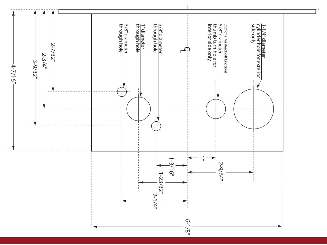
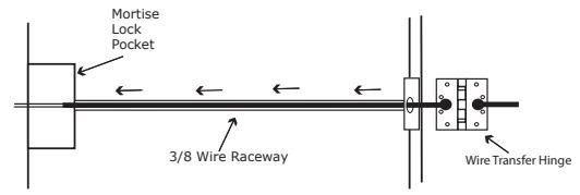
- 1. The door must be prepared with a standard type 86 mortise lock preparation and a 3/8" wire raceway. Be sure that the mortise pocket and the raceway are clear of debris prior to installation.
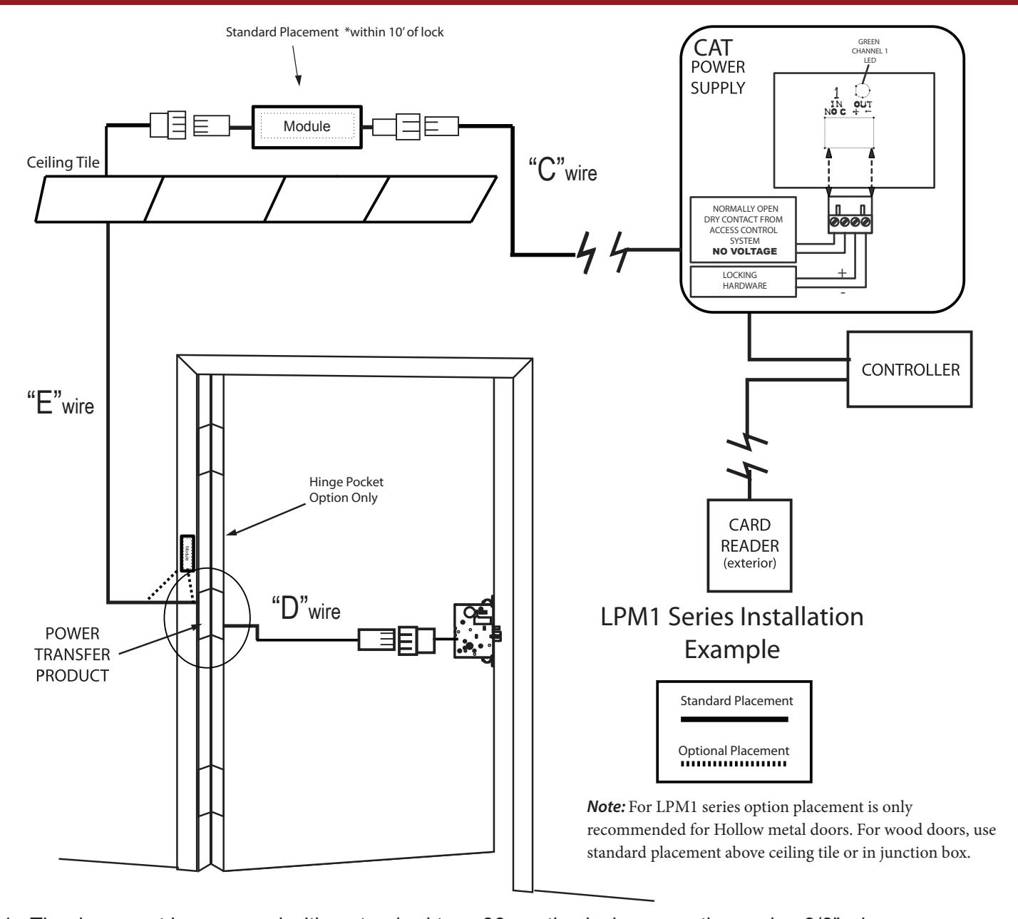
- 2. Install the "D" wire through the wire raceway leaving enough slack to "quick connect" to the mortise chassis.
- 3. Install PM300HO at the hinge jamb side of the door within 120" of the lockset. Connect wire "E" to the PM300HO and hard wire it directly to the harness from the lockset (if using an electric hinge or other transfer device, use 18ga wire).
- 4. Connect the 2-prong input power wires (BLACK and BLACK) of the PM300HO to wire "C". Then connect wire "C" directly to the wire run coming from the 26.5VDC power supply (not included). The power supply may be up to 300 feet away (see power supply wiring instructions). Note: these wires are not polarity sensitive.
I n s ta l l at i o n I n s t r u c t i o n s

For Lever Control Solenoid on LPM models 183-188 Only LPM110-182 Skip Section
Step 1 - The door must be prepped according to original manufactures template, machined with a 3/8" wire raceway, & prepped for a energy transfer hinge.
Make sure the mortise pocket is free of debris.
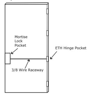
Step 2 - Run the wires from the ETH hinge through the 3/8" race way starting at the ETH hinge & exiting into the mortise pocket.
Step 3 - Screw the ETH hinge to the door. At this time DO NOT connect the hinge wires on the jamb side to the wires coming from the power supply.
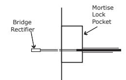
Step 4 - Connect the wires exiting the mortise pocket to the Bridge Rectifier (included).
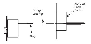
Step 5 - Connect the Bridge Rectifier to the plug exiting the mortise chassis.
- Step 6 Carefully slip the connected mortise lock chassis into the mortise pocket paying close attention not to pinch any wires
- Step 7 Mount the chassis per manufacturer's instructions.
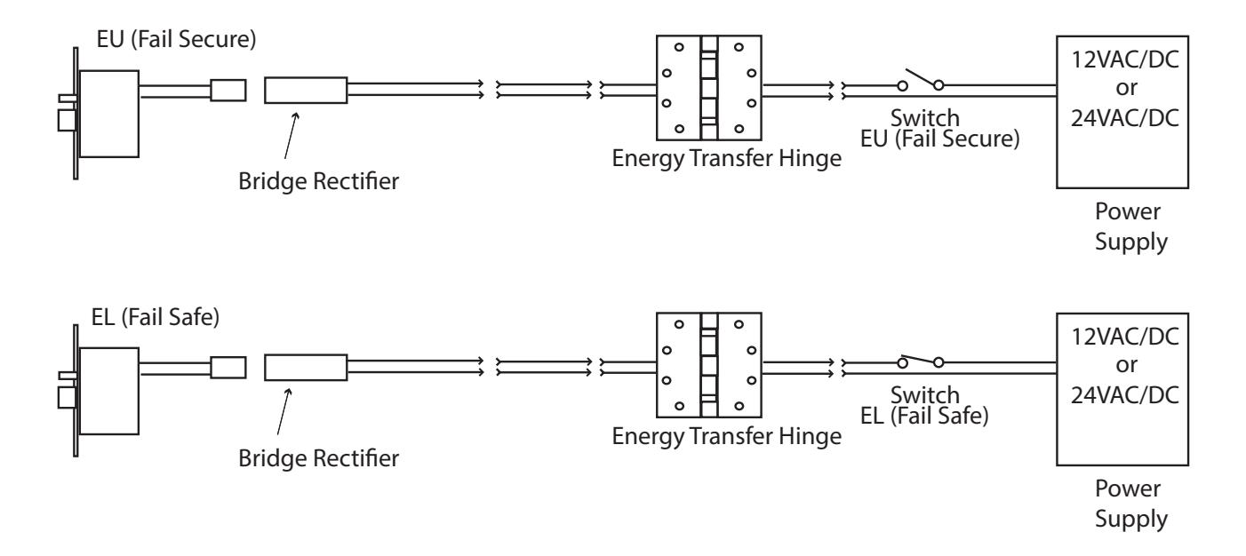
- Step 8 Connect the wires from the power supply at the ETH hinge on the jamb side. Connect the hinge to the jamb.
I n s ta l l at i o n I n s t r u c t i o n s

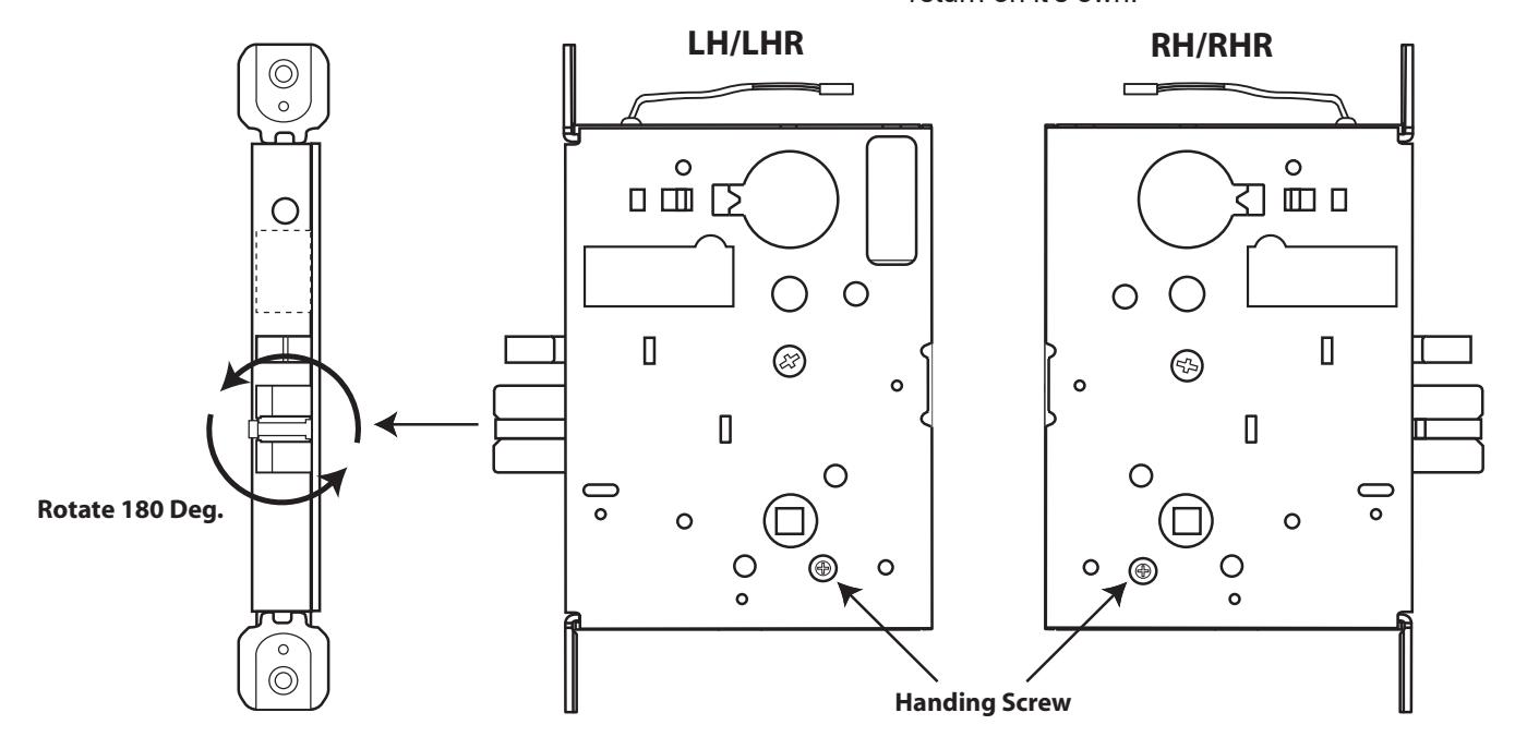
Handing Instructions
STEP 1: Locate the handing screw. This screw is used to hand the handles. The Locking side is opposite the screw.
STEP 2: To hand the latchbolt, remove the faceplate. Pull the latchbolt out of the chassis and rotate, then release. The latchbolt is spring loaded and will return on it's own.
Template for non-deadbolt & deadbolt