LP8600 X LR8600 & 12-LP8600 X 12-LR8600 (Double Egress & Double Doors) or LS8600 & 12-LS8600 (Single Door) Installation Instructions
Open the original PDF document
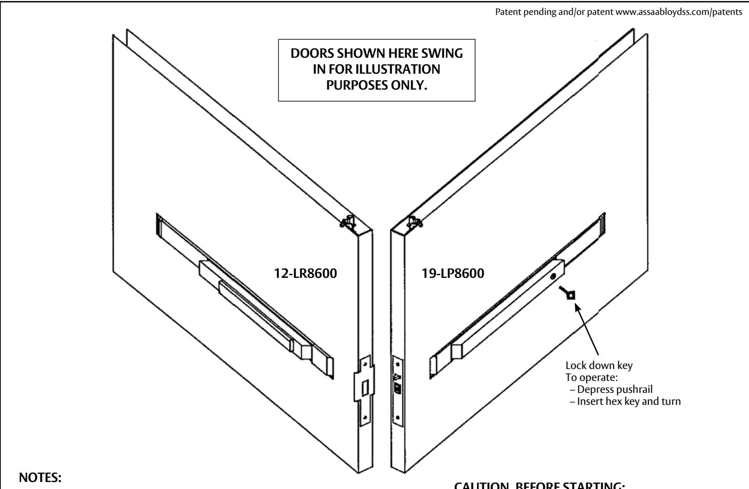
View PDFSARGENT Installation Instructions for LP8600 x LR8600 & 12-LP8600 x 12-LR8600 Series Low Profile Panic and Fire Exit Devices on Double Egress & Double Doors or LS8600 & 12-LS8600 Low Profile Exit Device on Single Door

For installation assistance, contact SARGENT at 800-727-5477 • www.sargentlock.com
- 1) The doors should be properly reinforced and should be fully prepared by the door manufacturer.
- 2) Rails can not be cut down in the field.
CAUTION, BEFORE STARTING:
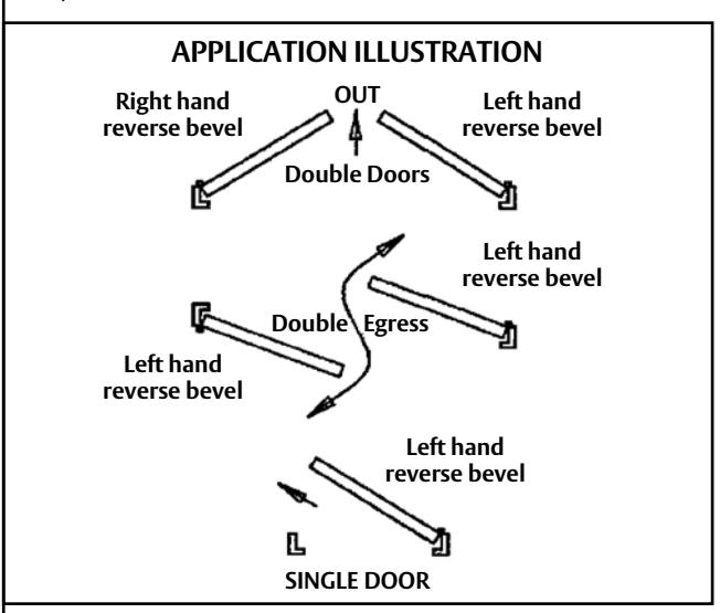
- Check hand of door LP8600 & LR8600 exit devices are non handed, ET trim is field reversible. LS86000 curved lip strike is handed.
- 2-3/4" backset only
- 1-3/4" thick doors only
- Verify box label for size, function and hand of exit device
- Available lengths: Length "L" for 36" wide doors Length "M" for 42" & 44" wide doors Length "N" for 46" & 48" wide doors
- Door should be fitted and hung unless low ceiling condition exists (For low ceiling conditions, install mortise lock and top rod before hanging door. Low ceiling exists if ceiling height is less than: (2 x door height) – mounting height i.e. 7' door with device mounted at 41" aff would need (2 x 7') – 41" or 10'7" ceiling.)
- Doors that are hung should be square and plumb. Clearance between the doors should be per the door manufacturers specification; i.e. gap between doors should be 1/4" at center line of bevels. (If gap is over 1/4" doors must be shimmed to decrease the gap.)
REQUIRED TOOLS:
Hammer Needle nose pliers #2 Phillips screw driver
#3 Phillips screw driver
Drill with 11/32" drill bit Locking pliers Flash light
Tape measure
A
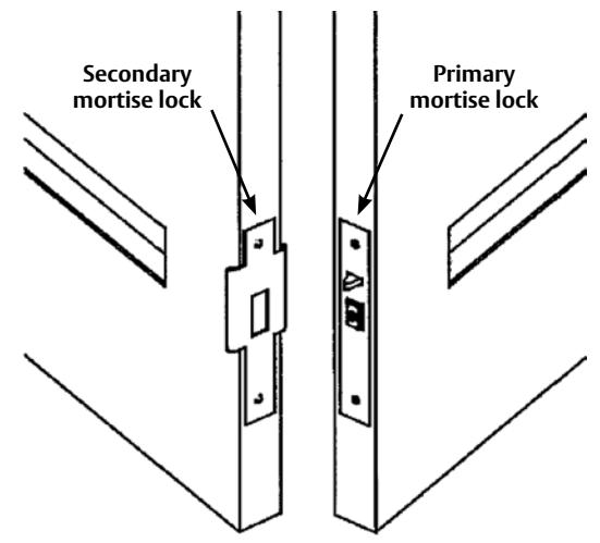
INSTALL MORTISE LOCKS
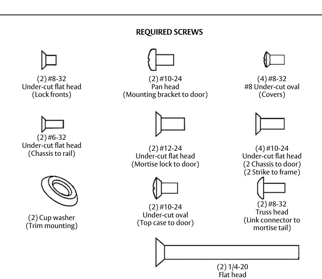
- 1) Mount primary and secondary mortise locks in doors with (2) #12 flat head machine screws provided.
- 2) Install outside fronts to mortise locks with (2) #8 flat head machine screws provided.
C ASSEMBLE TOP ROD AND EXTENSION
with step 2. Extension rod and bolt Connector Spiral pin Top rod Connecting tube
1) If rod assembly is in two pieces, continue If rod assembly is in one piece go, to part "D". 2) Slide rod together and align holes. 3) Secure with spiral pin.

INSTALL TRIM (IF APPLICABLE)
B
1) Using the appropriate portion of template A6381, supplied with trim, drill all required holes in the door. 2) Align the spindle with the outside hub and install ET trim. 3) Secure with 1/4-20 screws and cup washers. Outside hub Cup washer
D INSTALL TOP ROD ASSEMBLY
1) Insert rod assembly into door, as shown. 2) Align connecting tube with top mount. 3) Rotate rod assembly clockwise until bolt projects 1/4" above the door. Connecting tube Top mount Latchbolt tail NOTE: After rods are installed, doors can be blocked open until chassis is installed. If doors are closed and latched before chassis is installed, the bolts can be retracted from the inside by pulling the latchbolt tail toward the hinge.

2
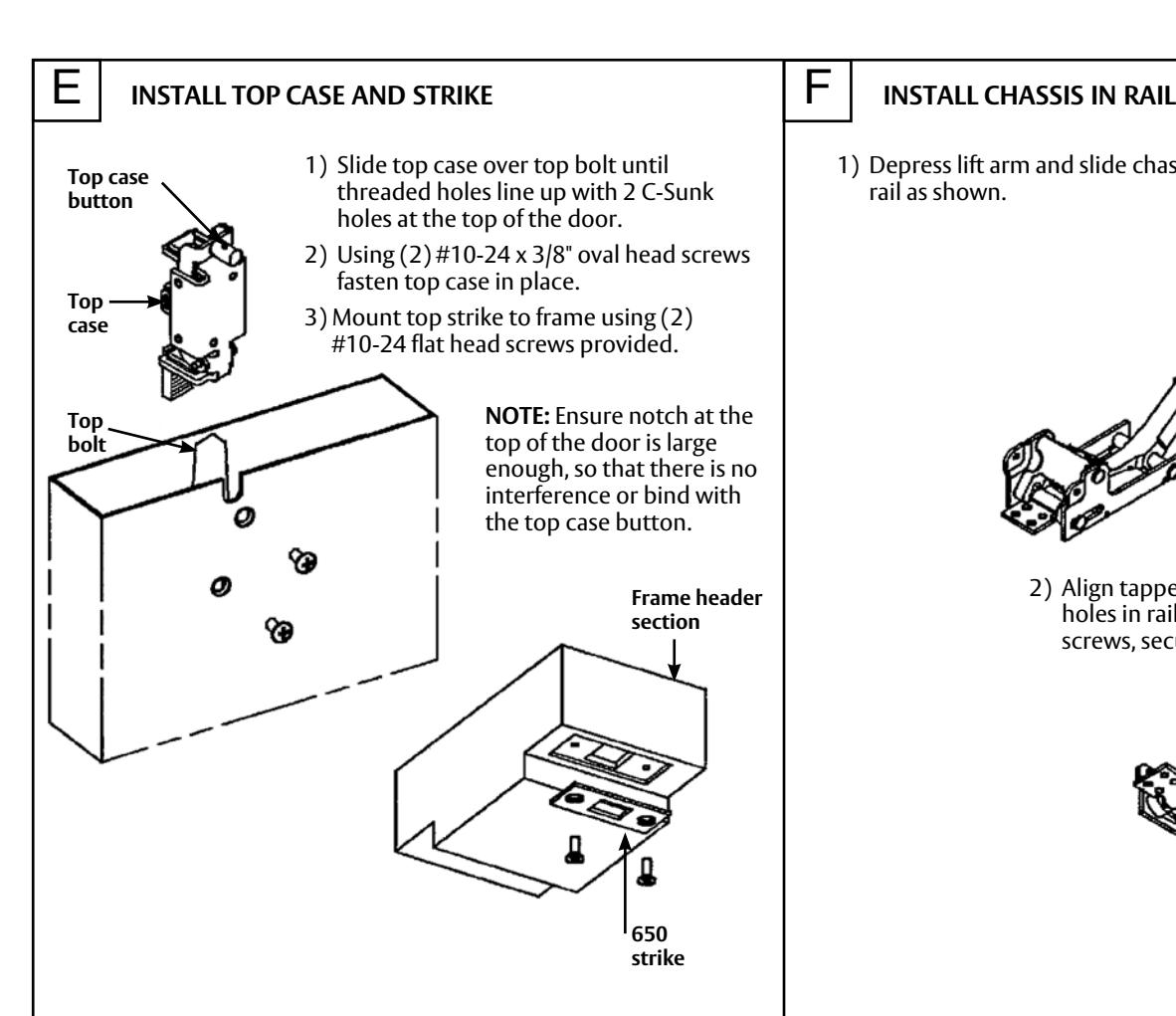
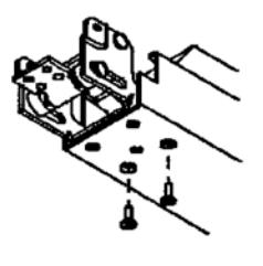
1) Depress lift arm and slide chassis into rail as shown.
2) Align tapped holes in chassis to C-Sunk holes in rail. Using (2) #6-32 flat head screws, secure chassis to rail.
G INSTALL RAIL
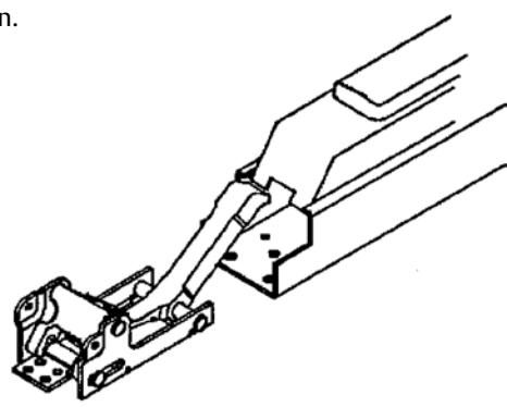
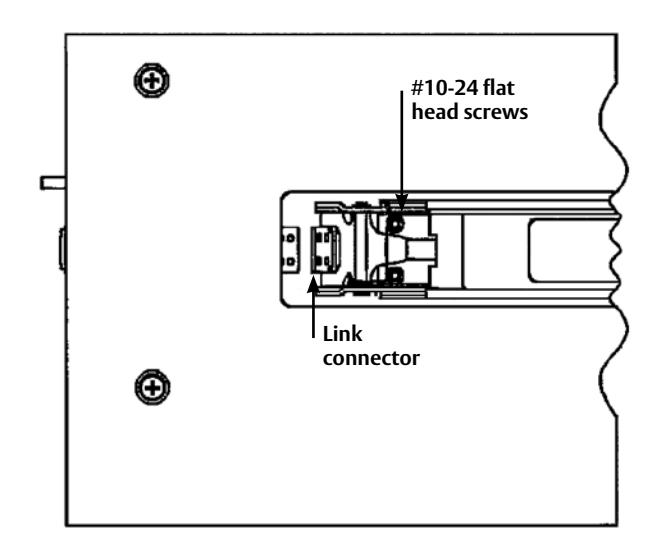
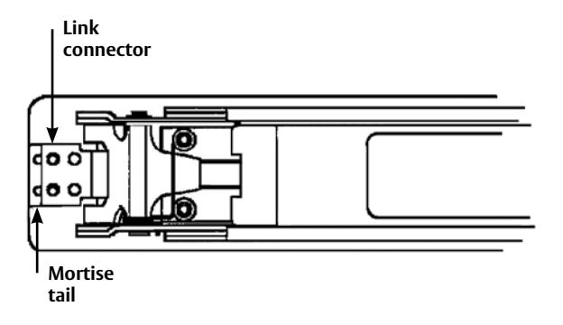
- 1) Rotate link connector up and place rail assembly in door cavity as shown.
- 2) Align C-Sunk holes in chassis with tapped holes in door and secure with (2) #10-24 flat head screws.
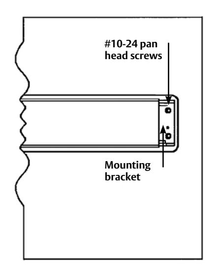
- 3) Position mounting bracket to support end of rail and secure with (2) #10-24 pan head screws.
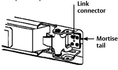
- 1) Rotate link connector down and pull toward mortise lock.
- 2) Align one pair of holes on link connector with mortise tail and secure using (2) #8 truss head screws.
REPEAT FROM PART "B" ON OPPOSITE DOOR.
J ADJUST PRIMARY MORTISE LOCK (LP8600)
- 1) With both doors closed, check for proper top and center latchbolt throw and engagement with strikes.
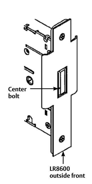
- 2) Depress push rail to retract latches and open door. If center bolt does not retract to clear the LR8600 outside front, adjustment is required.
- 3) Remove (2) #8 screws from linkage.
- 4) Rotate lever trim to align next set of holes.
- 5) Reinstall the #8 screws.
- 6) Repeat step 1 to verify adjustment.
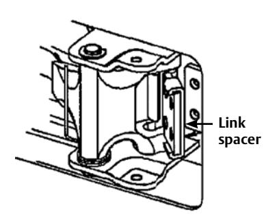
- 7) If binding condition occurs where top bolt remains retracted and center bolt remains retracted when door closes, remove the (2) #8 screws installed in part "H".
- 8) Install link spacer between the link connector and mortise tail. Reinstall #8 screws. Then repeat step 1.
H CONNECT LINKAGE I ADJUST SECONDARY MORTISE LOCK (LR8600)
- 1) Depress rail and observe center bolt. If bolt is projected, flush or just beyond outside front, adjustment is correct.
- 2) If adjustment is required, remove (2) #8 screws from linkage.
- 3) Rotate lever trim to align next set of holes.
4) Reinstall the #8 screws and repeat step 1.
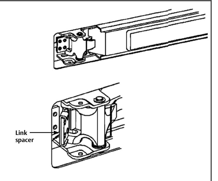
- 5) If binding condition occurs where top bolt remains retracted and center bolt remains extended when door closes, remove the (2) #8 screws installed in part "H".
- 6) Install link spacer between the link connector and mortise tail, reinstall #8 screws. Then repeat step 1.


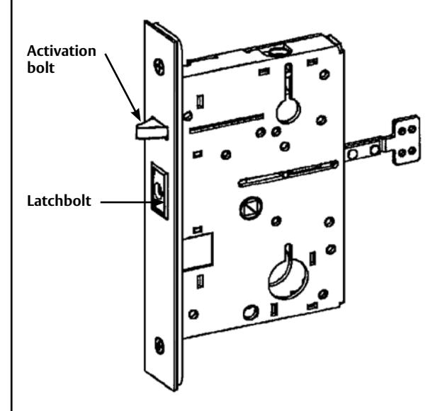
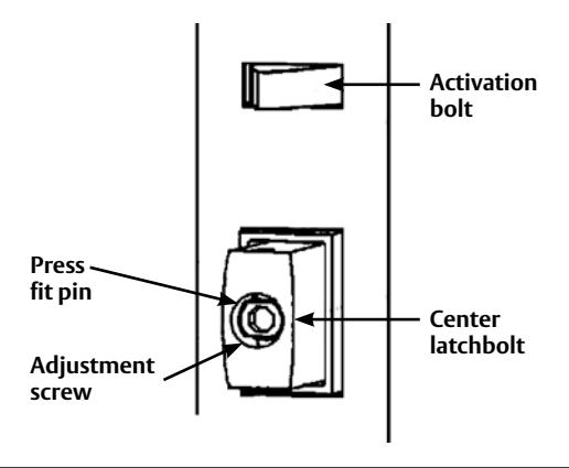
- 1) If there is not enough center latchbolt projection and engagement into the other door, the center bolt can be adjusted.
- 2) Open door and depress the activation bolt to project the latchbolt.
- 3) Using locking pliers, grip the latchbolt near the lock front.
- 4) Insert a 5/32" allen wrench into the latchbolt. Pull the latchbolt out until you can freely turn the adjusting screw.
- 5) To increase projection, turn the adjusting screw counterclockwise. To decrease projection, turn the adjusting screw clockwise. When desired projection is achieved, rotate the adjusting, screw so the flats are aligned with the 2 press fit pins.
- 6) Release the pliers and allow the latchbolt to snap back.
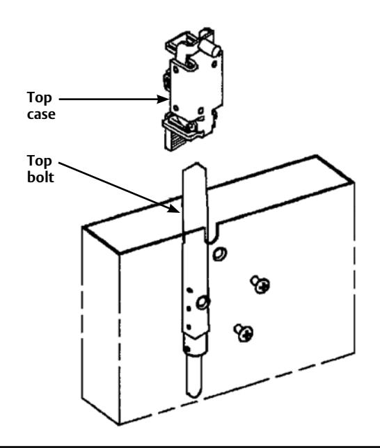
K CENTER BOLT ADJUSTMENT L TOP BOLT ADJUSTMENT
- 1) If there is not enough top latchbolt engagement into top strike to latch the door securely, complete the following steps:
- 2) Remove top case from door and rotate the top bolt counterclockwise to increase projection.
- 3) Reinstall top case, and recheck the adjustment.
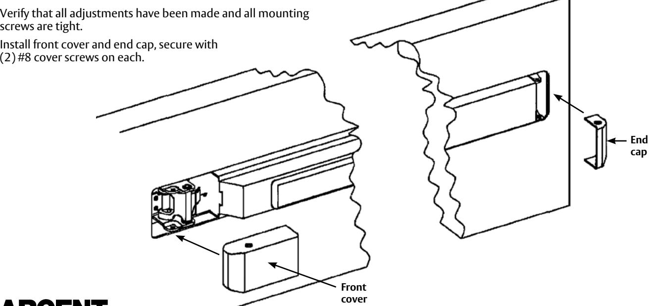
M OPERATION VERIFICATION
- 1) Open and close doors several times in different sequences to ensure proper operation and latch engagement into strikes. Center latchbolt should project into opposing door regardless of closing order.
- 2) If bolts are not retracting or projecting properly, review/repeat parts I thru L.


2) Install front cover and end cap, secure with
Copyright © 2009, 2010, 2016, Sargent Manufacturing Company, an ASSA ABLOY Group company. All rights reserved. Reproduction in whole or in part without the express written permission of Sargent Manufacturing Company is prohibited.
SCREW PACKS AND MISCELLANEOUS PARTS
(Trim mounting)
| 68-1317 | Front cover (Finished) |
| 68-1316 | End cap (Finished) |
| 01-0696 | Spiral pin |
| 68-1186 | Primary outside front |
| 68-1183 | Secondary outside front |
| 77-0883 | Curved lip strike (Left hand) |
| 77-0884 | Curved lip strike (Right hand) |
| 650 | Top strike pack |
| 77-4236 | Screw pack (Mortise lock) |
| 68-4373 | Screw pack (Chassis) |
| 68-3677 | Screw pack (Top case) |
| 68-4383 | Screw pack (Mounting plate) |
| 651 Kit | Lexan touch pad |
| 816 | Cylinder dogging kit |
FOR ADDITIONAL INFORMATION CONTACT SARGENT AT 1.800.727.5477