LCN_Senior_Swing_Series_Push_Arm_&_Link_Assembly_Installation_Instructions_107503
Open the original PDF document
View PDF

Push Arm & Link Assembly Installation Instructions

Models 9540, 9550, 9560
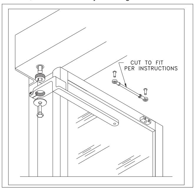
Push Arm Installation
- 1a Install the header and door bracket using the appropriate template.
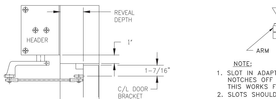
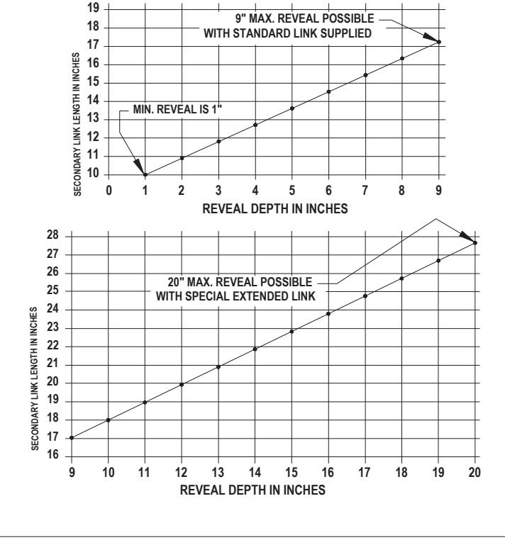
- 1b Using the appropriate chart, measure and cut the exact length required for the threaded rod. Threaded rod length is determined by measuring the reveal dimension (in inches) from the surface of the door to which the arm is attached to the back surface of the header. Using the horizontal scale (calibrated in inches and quarter inches), follow the vertical line of the reveal dimension upwards until it intersects the slanted line. Reading to the left of the vertical scale will determine the exact length (between centers of the turnbuckles) of threaded rod required. DO NOT CUT THE THREADED ROD FROM THE END WITH THE HOLE!
- L NOTE: The operator spindle is normally at the full breakout position (-90º). The arm must be attached to the spindle at the full open position (+90º).
- 1c Turn on power to the operator and momentarily short the activation wires together. The spindle will begin to slowly rotate to the open position. When the spindle stops rotating, momentarily short the activation wires together again. Continue this process until the spindle has reached the full open position (+90º).
- 1d Once the spindle is at the full open position (+90º), wire nut the activation wires together.
- 1e Install the spindle adapter into the arm as required. (See appropriate template.)
- 1f Install the arm onto the spindle at the full open position (+90º) and tighten cap screw.
- 1g Screw the threaded rod into the turnbuckles.
- 1h Remove the wire nut from the activation wires.
- 1i Connect activation wires to activation device.
- 1j Test door operation.
- 1k If no further adjustments are needed, secure the arm by installing the washer and screw.

Installation Template Offset Pivoted or Butt Hinged Doors

Installation Template 2 3/4" Center Pivoted Doors

Installation Template 3 3/4" Center Pivoted Doors
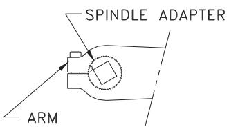
- 1. SLOT IN ADAPTER IS FACTORY INSTALLED TWO NOTCHES OFF CENTER LINE AS SHOWN. THIS WORKS FOR ALL STD. APPLICATIONS
- 2. SLOTS SHOULD NEVER BE MIS-ALIGNED MORE THAN FIVE NOTCHES EITHER WAY.

FOR SURFACE APPLIED OPERATORS WITH PUSH ARMS ON 3-3/4" CENTER PIVOTED DOORS
Customer Service
1-877-671-7011
www.allegion.com/us