LCN_4840_Series_Installation_Instructions_107125
Open the original PDF document
View PDF

4840 Auto-Equalizer

25381
Non-Handed/Non-Sized/Low Energy Installation And Adjustment Of Door Operator
Installation Instructions

General Information
This door operator requires these additional system components:
7900 or 7980 series Control Box
- 459 Pnuematic Door Loop Kit, (4 1/2 " maximum reveal depth, see page 6) or
- 460 Pnuematic Transfer Hinge Kit (see page 6)
Push & Pull side actuator devices (switches)
NOTE: 460 Transfer Hinge requires an interior door raceway between transfer hinge and 4840 Auto - Equalizer®
Requirements:
Minimum door width is 24" Minimum door top rail is 4 1/2" Minimum stop width is 1"
Flush or single rabbeted frames require a - 418 FPA
Arm Options:
EDA (standard), Cush N Stop or Spring Cush

2 Operator Installation
- ① NOTE: If using the 460 transfer hinge, install at this time. See page 6 for details.
- 2a Prepare door & frame per template on page 7. Drill and/or tap holes to receive 1/4 20 machine screws or No. 14 wood screws. Use fasteners provided by LCN to keep warranty valid.
- 2b Remove operator assembly from mounting plate, as shown in Figure 1 above. Install mounting plate on door using (6) 1/4 20 x 5/8" machine screws or (6) No. 14 x 1 1/2" wood screws provided. Reattach operator assembly.
- 2c Place arm on the top of closer shaft with main arm parallel to the door. Place wrench on the bottom of the closer shaft and rotate toward hinge approx. 30°. See Figure 2 . Main arm can now be placed on to closer shaft. Secure with arm screw.
- ① NOTE: If installed properly, main arm will rest against door.
- Swing door open about 45°. Using the fasteners provided, mount shoe to frame stop per proper templating on page 7. Be sure to install the "fifth" screw. If stop is not wide enough, use spacer block provided or cush shoe support shown on page 7.
- 2e Connect air line to air inlet fitting, then feed other end toward control box by either using the 15" pneumatic door loop or the pneumatic transfer hinge (see page 6).

3 Closing Force Adjustment (see Figure 3)
3a To adjust Closing Force , turn the spring adjustment nut clockwise or counter-clockwise the required number of turns to match the door width in Tables 1 & 2 . Maximum adjustment, 5 turns counterclockwise and 7 turns clockwise.
CAUTION
Do not set door speed faster than chart recommends.
4 Closing Speed Adjustment (See Figure 3)
- 4a THE 4840 SERIES CLOSER HAS BEEN REGULATED PRIORTO SHIPMENT. If regulation adjustments are needed use 3/32 Hex wrench furnished, and refer below.
- 4b A "normal" closing time from 90° open position is 5 to 7 seconds, evenly divided between Main Speed and Latch Speed .
- 4c To slow Main Speed of door, turn regulating screw (nearest to arm) clockwise.
- 4d To slow Latch Speed of door, turn regulating screw (nearest to latch) clockwise.
- 4e Do not allow door to slam into frame.
5 Backcheck Adjustment
5a Backcheck slows the door swing as it approaches full opening (see Figure 3) .
5b Increase the resistance of backcheck only if necessary to prevent the door from striking a wall. To do this, turn the regulating screw (nearest to hinge) clockwise by quarter turns. DO NOT USE AN ABRUPT BACKCHECK .
Table 1
| Exterior Door | |||
|---|---|---|---|
| Maximum Door Width | Number of Turns | ||
| 30" | 0 Turns | ||
| 36" | 2 Turns C.W. | ||
| 42" | 7 Turns C.W. | ||
Table 2
| Interior Door | ||||
|---|---|---|---|---|
| Maximum Door Width | Number of Turns | |||
| 34" | 5 Turns C.C.W. | |||
| 38" | 0 Turns | |||
| 48" | 2 Turns C.W. | |||
| 54" | 7 Turns C.W. | |||

- L NOTE: For air pressure regulation, see control box instructions.
- 6a The door opening speed must be adjusted to suit the width and weight of door. The wider and / or heavier the door, the slower it should open. To determine opening speed, measure door width and weight and set speed to open door from 0° to 80° for the time shown in Table 3 below. The opening speed control adjusting screw is located in the end of the door operator near the tubing connection (see Figure 4) . Using a 3/32" hex wrench (provided), turn the speed control clockwise to slow the door, counterclockwise to increase door speed.

Table 3
|
Door Weight
in Pounds |
Fastest Opening Time in Seconds to 80°
Position Door Width in Inches |
||
|---|---|---|---|
| 36" | 42" | 48" | |
| 100 lbs. | 3.0 sec. | 3.0 sec. | 3.0 sec. |
| 125 lbs. | 3.5 sec. | 3.5 sec. | 3.5 sec. |
| 150 lbs. | 3.5 sec. | 3.5 sec. | 3.5 sec. |
| 200 lbs. | 4.0 sec. | 4.0 sec. | 4.0 sec. |
- L NOTE: If door width or weight is between the sizes and pounds listed, use the time shown for the next wider or heavier door.
- 6b If door weight cannot be measured, the weight can be estimated by finding the area of the door (length x width) and multiplying it by the weight per square foot for the door type that is being used, as shown in Table 4 below.
Table 4
| Door Type | Weight per Sq. Ft. |
|---|---|
| Solid Core Wood | |
| 20 Ga. Flush Hollow Metal | 5.5 |
| Aluminum x 1" Glass | |
| Mineral Core Door | |
| 16 Ga. Flush Hollow Metal | 7.0 |
| Aluminum x 1" Glass |
7 Delay Time Adjustment
After opening, the door should remain at the 90° position for no less than 5 seconds. This "Delay Time" can be increased to approximately 30 seconds by turning the timer adjustment wheel(s) clockwise. For the location of this wheel(s), refer to 7900 or 7980 Series Control Box Instruction Sheet. Adjust "Delay Time" to maximum practical for the elderly or handicapped. Time cycle begins when switch or scanner is activated.
8 Attach Cover
- 8a Slide cover insert into the bottom cutout in cover (see Figure 5) .
- 8b Push cover over the operator assembly and against mounting plate.
- 8c Insert cover screws and tighten securely.
9 Locating the Caution/Automatic Door Decal
- 9a Locate one decal on each side of door near lock stile of door, approximately 18" min. to 42" max. above the floor. The decal location must be visible without interference from door trim, panic devices, etc.
- 9b Clean a 6" x 6" area where decals will be placed.
- 9c Apply one decal (item 16 on page 10) on each side of the door. Remove backing and "roll" onto door to avoid trapping air under decal.

Concealed or Surface Air Transfer Options
10 Pneumatic Door Loop Installation (see Figure 6)
- (i) See page 8 for template
- (i) Reveal must be less than 4 1/2"
- 10a Remove the cover end cap (closest to hinge stile of door) by removing the (2) Phillips head screws from inside the cover.
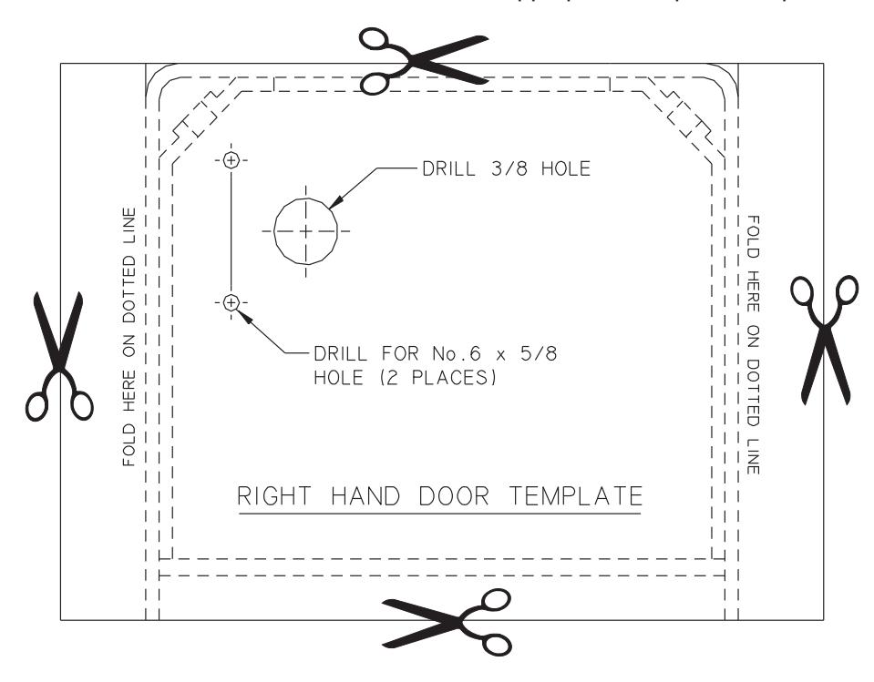
- 10b Place the proper hand template (see cutouts on page 11) over the end cap and tape down securely.
- 10c Once the template is in place, drill (1) 3/8" hole, and (2) 1/16" holes in the proper location.
- 10d After holes are drilled, remove template and place end cap back on the cover.
- 10e Feed 1/4" tubing through the drilled end cap and also through the 15" aluminum tubing supplied with kit.
- 10f Place 90° door loop cap on cover end cap (making sure to line up slots over the ends of the 15" tubing) and secure with No.6-32 screws provided.
- 10g Feed the 1/4" tubing (either 180° up the frame, or 90° into the frame), place the concealed 90° or the surface 180° (depending on the installation) door loop cap over end of the 15" aluminum tubing and secure to the frame of the door. (See Figure 6).

11 Pneumatic Transfer Hinge Installation (see Figure 7)
- ① A INTERIOR RACEWAY FROM TRANSFER HINGE TO 4840 CLOSER IS REQUIREDTO USE THIS PRODUCT, SEE PAGE 9 FOR TEMPLATE.
- 11a Apply pneumatic transfer hinge housing using No. 8-32 machine screws provided.
- 11b Connect tubing using the inline tubing splice provided
- 11c Apply transfer hinge unit using No.10-24 machine screws provided.
- 11d Check operation of pneumatic transfer hinge unit.
① NOT FOR USE WITH SWING CLEAR HINGES OR CENTER PIVOTS!


| Item No. | Part No. | Description | Quantity |
|---|---|---|---|
| 1 | 925 | 1/8 " I.D. Pneumatic Tubing | 5' or 12' Section |
| 2 | 4810-18 | Standard Mounting Plate | 1 |
| 3 |
No. 14 x 1 1/2"
1/4-20 x 5/8" |
Phillips Head Wood Screw or
Phillips Head Machine Screw |
6 |
| 4 | 4810-182 | Standoff | 2 |
| 5 | 4840-3071 | LCN Switch-Actuated Auto Equalizer | 1 |
| 6 | 1/4-20 x 2 1/2" | Phillips Head Machine | 4 |
| 7 | 4810-159 | Arm Shaft S | 1 |
| 8 |
4040SC-3035
4040EDA-3035 4040CNS-3035G |
Spring Cush Arm Assy.
Extra Duty Parallel Arm Assy. Nonhanded Cush-N-Stop Assy. |
1 |
| 9 |
1/4-20 x 5/8"
1/4-20 x 1 1/2" No.14 x 2 " |
Phillips Head Machine Screw
or Phillips Head Machine Screw Phillips Head Wood Screw |
4
1 5 |
| 10 | 4840-72 | Cover | 1 |
| 11 | 4840-163 | Cover Insert | 1 |
| 12 | 4810-31L | Long Cover Screw | 2 |
| 13 | 4810-31 | Cover Screw | 2 |
| 14 | 7900 or 7980 | Control Box | 1 |
| 15 | 920 Series | Compressor (optional) | 1 |
| 16 | 4820-155G | Decal | 2 |
| 17 | 4840-459 | Pneumatic Door Loop Kit (optional) | 1 or |
| 18 | 4840-460 | Pneumatic Transfer Hinge Kit (optional) | 1 |
If the proper hand door has been determined, cut out the appropriate template and place on the end cap.