LCN_4820_Series_Installation_Instructions_107122
Open the original PDF document
View PDF

4820 Series

24828
Non-Handed/Non-Sized Auto-Equalizer Low Energy Door Operator, Installation and Adjustment of Door Operator
Installation Instructions
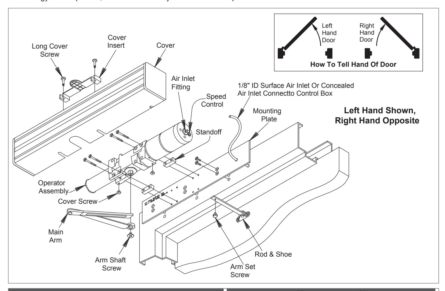
1 Installation
- NOTE: This door operator requires additional system components, see LCN Closer Catalog.
- 1a Prepare frame per template (page 6), then secure mounting plate to frame with screws provided.
- 1b Secure operator assembly to mounting plate with 1/4-20 x 21/2 P.H.M.S.
- 1c Connect air line to air inlet fitting.
- 1d Place main arm on operator shaft 100° to operator assembly and secure with shaft screw.
- 1e Attach rod and shoe to door.
- 1f Open door, insert rod in forearm tube, close door.
- 1g With rod and shoe at right angle to door, insert forearm set screw and tighten securely.
A CAUTION A
Improper installation or regulation may result in personal injury or property damage. Follow all instructions carefully. For questions, call LCN at 877 - 671 - 7011.
Customer Service
1-877-671-7011 www.allegion.com/us

© Allegion 2016 Printed in U.S.A. 24828 Rev. 06/16-h
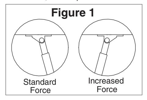
2 Closing Force Adjustment
- 2a To adjust CLOSING FORCE, use B\cx" allen wrench to turn the spring adjustment clockwise or counterclockwise the required number of turns to match the door width in the tables in Step 3. Maximum adjustment: 3 turns counter-clockwise and 10 turns clockwise.
-
2b ADJUSTMENT FOR ADDITIONAL CLOSING FORCE AT LATCH. (See Fig. 1)
- a. Remove forearm set screw and separate rod from tube.
- b. Remove shoe screws and turn shoe over.
- c. Reassemble arm, as in steps 6 & 7 of installation.
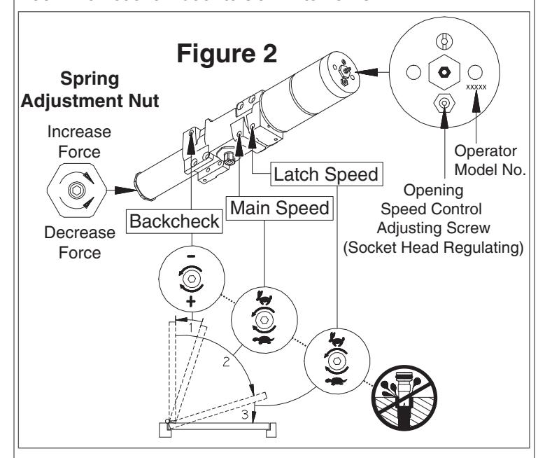
- 3 Closing Speed Adjustment (see Fig. 2)
- 3a A "normal" closing time from 90° open position is 5 to 7 seconds, evenly divided between main speed and latch speed
- 3b Use C\cx" allen wrench provided.
- 3c To slow MAIN SPEED of door, turn regulating screw (nearest to arm) clockwise.
- 3d To slow LATCH SPEED of door, turn regulating screw (nearest to latch) clockwise.
- 3e Do not allow door to slam into frame.
| Exterior Door | |||||
|---|---|---|---|---|---|
| Maximum Door Width | Number of Turns | ||||
| 30" | 0 Turns | ||||
| 36" | 2 Turns C.W. | ||||
| 42" | 7 Turns C.W. | ||||
| Interior Door | |||||
|---|---|---|---|---|---|
| Maximum Door Width | Number of Turns | ||||
| 34" | 3 Turns C.C.W. | ||||
| 38" | 0 Turns | ||||
| 48" | 2 Turns C.W. | ||||
| 54" | 7 Turns C.W. | ||||
4 Opening Speed Adjustment
- L NOTE: For air pressure regulation, see control box instructions.
- 4a The door opening speed must be adjusted to suit the width and weight of door. The wider and/or heavier the door, the slower it should open. To determine opening speed, measure door leaf width and weight and set speed to open door from 0° to 80° for the time shown in the table below. The opening speed control adjusting screw is located in the end of the door operator near the tubing connection (see Figure 2). Using a C\cx" allen wrench (provided), turn the speed control clockwise to slow the door, counter clockwise to increase speed.
| Door Weight in | FASTEST OPENINGTIME 0° to 80° | |||||
|---|---|---|---|---|---|---|
| Pounds | DOOR WIDTH IN INCHES | |||||
| 36" | 42" | 48" | ||||
| 100 lbs. | 3.0 sec | 3.5 sec | 4.0 sec | |||
| 125 lbs. | 3.5 sec | 4.0 sec | 4.5 sec | |||
| 150 lbs. |
3.5 sec
200 lbs. 4.0 sec |
4.5 sec | ||||
| 5.5 sec | ||||||
L NOTE: If door width or weight is between the sizes and pounds listed, use the time shown for the next wider or heavier door.
CAUTION
DO NOT SET DOOR SPEED FASTER THAN CHART RECOMMENDS.
4b If door weight cannot be measured, the weight can be estimated by finding the area of the door (length x width) and multiplying it by the weight per square feet for the door type that is being used as shown in the table below.
| Type of Door | Weight per Sq. Ft. |
|---|---|
| - Solid Core Wood | 5.5 lbs |
| - 20 Ga.Flush Hollow Metal | |
| - Aluminum x Z\v" Glass | |
| - Mineral Core Door | 7.0 lbs |
| - 16 Ga.Flush Hollow Metal | |
| - Aluminum x 1" Glass |
L NOTE: These weights are for 1 C\v" thick doors. If the doors are thicker or thinner, consult door manufacturer for proper weight, or weigh the door.
5 Backcheck Adjustment
- 5a Backcheck slows the door swing as it approached full opening (see Figure 2 on page 2).
- 5b Increase the resistance of backcheck only if necessary to prevent the door from striking a wall. To do this, turn the regulating screw (nearest to hinge) clockwise by quarter turns. DO NOT USE AN ABRUPT BACKCHECK.
6 Delay Time Adjustment
After opening, the door should remain at the 90° position for no less than 5 seconds. This "Delay Time" can be increased to approximately 30 seconds by turning the timer adjustment wheel(s) clockwise. For the location of this wheel(s), refer to 7900 or 7980 Series Control Box Instruction Sheet. Adjust "Delay Time" to maximum practical for the elderly or handicap. Time cycle begins when switch or scanner is released.
7 Attach Cover
- 7a Slide cover insert into the top cutout in cover (see Figure 3).
- 7b Push cover over the operator assembly and against mounting plate.
- 7c Insert cover screws and tighten securely.

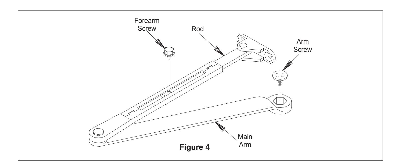
8 9 Locating The Caution/Automatic Door Decal Double Lever Arm Set Screw Adjustment Local one decal on each side of the door near lock It may be necessary to adjust the fully open door position. Minor stile of door, approximately 18" min. to 42" max. above adjustment can be obtained by using the telescoping arm as the floor. The decal location must be visible without follows (see Figure 4): interference from door trim, panic devices, etc. Shorten length of arm to decrease door opening. Clean area 6" x 6" where decals will be placed. 8b Lengthen arm to increase door opening. Apply one decal (item 17 on page 5) on each side of Loosen arm set screw and adjust arm to preferred door. Remove backing and "roll" onto door to avoid length. trapping air under decal. 9c Tighten arm set screw securely after adjustment. After arm adjustment is made, cycle door to insure that it is operating properly. AUTOMATIC

| Item No. | Part No. | Description | Quantity |
|---|---|---|---|
|
1
925 |
Z" I.D. Pneumatic Tubing | Order Length Required | |
| 2 | 4810-18 | Standard Mounting Plate | 1 |
| 4820-18G | Flush Ceiling Mounting Plate | ||
| 3 | No. 14 x 1Z\x" | Phillips Head Wood Screw or | 8 |
| 1/4-20 x 5/8" | Phillips Head Machine Screw | ||
| 4 | 4820-182 | Standoff | 2 |
| 5 | 4820-3071 | LCN Switch-Actuated Auto Equalizer ® | 1 |
| 6 | 1/4-20 x 2Z\x" | Phillips Head Machine Screw | 4 |
| 7 | 4820-77 | Main Arm & Forearm | 1 |
| 8 | 4020-159 | Arm Screw | 1 |
| 9 | 4820-79 | Rod & Shoe | 1 |
| 10 | 4820-83 | Arm Set Screw | 1 |
| 11 | 4820-72 | Cover | 1 |
| 12 | 4820-163 | Cover Insert | 1 |
| 13 | 4820-31 | Cover Screw | 2 |
| 14 | 4820-31L | Long Cover Screw | 2 |
| 15 | 900 or 7980 Series | Control Box | 1 |
| 16 | 900 or 921 | Compressor (optional) | 1 |
| 17 | 4820-155G | Decal | 2 |
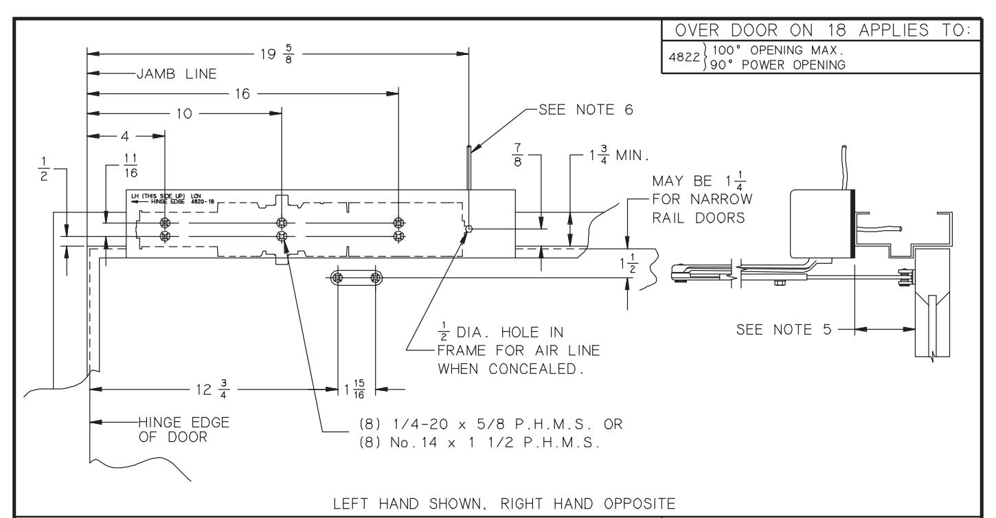
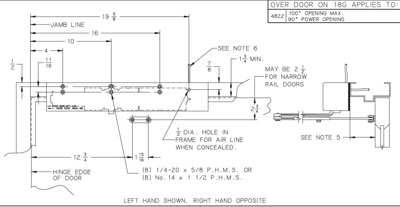
GENERAL NOTES-
- 1. MOUNT PROPER SIDE OF MOUNTING PLATE PER HAND OF DOOR.
- 2. MOUNTING SCREWS No.14 W.S. OR 1/4 20 M.S
- 3. CLOSER SIZE 20 x 3 x 3
- 4. LOCATE OPERATOR & SHOE FROM & OF PIVOTS OR SWING CLEAR HINGE WHEN USED.
- 5. STANDARD ARM ACCOMMODATES REVEALS UP TO 4 1/2". REVEALS FROM 4 1/2" TO 8" USE OPTIONAL LONG ROD & SHOE.
- 6. I.D. TUBING CONNECTED TO CONTROL BOX.
- 7. MAXIMUM BUTT SIZE 5"x 5"
| INCH | 1/2 |
1
1
16 |
7 8 |
1 15
16 |
2 1/2 | ||||
|---|---|---|---|---|---|---|---|---|---|
| ММ | 13 | 18 | 22 | 32 | 38 | 44 | 49 | 64 | |
| INCH |
3
|
3 1/2 | 4 | 10 |
12
|
16 |
19
|
20 | |
| М.М. | 70 | 84 | 89 | 102 | 254 | 324 | 406 | 498 | 508 |
| No. | REVISION | ВҮ | DATE | ICN | APP JEJ 6/96 |
|---|---|---|---|---|---|
| 2 | TEMPLATE UPDATE | JEJ | 6/96 | DO NOT SCALE | |
|
PUSH SIDE/TOP JAMB MOUNTED
AUTO-EQUALIZER® ON 18 OR |
NON-HANDED
18G PLATE |
||||
| 4820 |