LCN_2800_Series_and_9500_Series_Senior_Swing_Control_Box_Instruction_Sheet_107510
Open the original PDF document
View PDF

72937
Senior Swing Control Box

Installation Instructions
2800 Overhead Consealed Series 9500 Surface Applied Series
IMPORTANT
These instructions are presented in step-by-step sequence. It is very important that installation begins with "1. Pre-Installation Site and Product Check" (page 3) and continues as directed after each section.
WARNING
Always disconnect main power to the operator prior to replacing.
Control box contains no serviceable parts inside.
Table of Contents
| General Information 1 | |
|---|---|
| Electrical Specifications 2 | |
| 1 Pre-Installation Site and Product Check 2 | |
| 2 Installation 3 | |
| 3 Wiring 3 | |
| 4 Keypad Settings 7 | |
| 5 System Test11 | |
| 6 Troubleshooting 12 | |
| 7 Release for Service 13 |
General Information
The Senior Swing Control Box is for use with the Senior Swing Power Operator System. The system can operate a single door (2810, 9530, and 9540 Series), a simultaneous pair of doors (2850 and 9550 Series), or an independent pair of doors (2860 and 9560 Series).
ANSI/BHMA A156.19 Compliance
The Senior Swing Power Operator System is a low energy product and must conform to the latest version of ANSI/BHMA A156.19 (American National Standard for Power Assist and Low Energy Power Operated Doors).
Installation Instructions
All installation instructions are valuable references and should be given to the building owner or maintenance supervisor after installation is complete.
The Senior Swing Control Box installation instructions and the manufacturer's instruction manual accompanying any sensor must be referenced to ensure proper installation, setup, and operation.
Electrical Specifications
| AC input voltage | . 120 VAC |
|---|---|
| AC fuse | . 120 VAC, 2.5 A time-delay fuse |
| Motor protection | . Solid state failure detection and shutdown |
| Activate inputs | dry NO contacts (close contacts to open door) |
| Safety inputs | dry NO contacts (closed contacts indicate an obstruction) |
| Breakaway input | dry NC contacts (open contacts indicate breakaway) |
| 3-position switch input | . dry 3-position switch |
| Power Boost disable input | dry NO contacts (close contacts to disable Power Boost) |
| Lock output | . Form C dry relay contacts rated 8 A, 30 VDC maximum |
| Accessory power output | . 24 VDC, 1A (protected by resettable thermal fuse) |
| Logic power output | . 5 V, 50 mA (protected by resettable thermal fuse) |
1 Pre-Installation Site and Product Check
| À IMPORTANT À | ||||||
|---|---|---|---|---|---|---|
| Factory Authorized Door Leaf Size and Weight | ||||||
| Type | Width per Leaf | Maximum Weight per Leaf | ||||
| Single Door | 36" to 48" | 200 lb. (36 in. @ 400 lbs.) | ||||
| Simultaneous Pair | 30" to 48" | 200 lb. (36 in. @ 400 lbs.) | ||||
- 1a All required installation steps listed before "8. Control Box Installation" in the Senior Swing installation instructions should be completed before installing the Senior Swing control box.
- 1b Check that the control box model (indicated on control box label; Figure 1-1) is correct for the application.
- 1c Check that the available AC voltage matches the control box voltage requirement (120 VAC).
- 1d Check that all accessories required for the application are on hand.

2 Installation
To install the Senior Swing Control Box, follow the Senior Swing installation instructions beginning with "8. Control Box Installation" on page 12 of those instructions.
CAUTION
Improper installation or set up may result in personal injury or property damage. Follow instructions carefully. For answers to questions, call 1-877-671-7011
3 Wiring
- Review the separate wiring diagrams in the accessory instructions so that all wiring can be completed.
- See Figure 3-1 for system configuration terminology.
- See Figure 3-2, Figure 3-3, and Figure 3-4 for names and locations of control box connectors.
- See Figure 3-5 for control box plug and jack descriptions, wiring, and mating cables.
- See Figure 3-6 for electric strike locking device sample wiring.
- See Figure 3-7 for EL (electric latch retraction) locking device sample wiring.
CAUTION
When joining or separating a plug and receptacle, do not push or pull on wires. This may cause a wire to be pulled loose from a terminal, which may result in a malfunction.


Figure 3-2. Control box power board connectors.

Figure 3-3. Control box logic board connectors.

Figure 3-4. Closeup of control box logic board connectors.

L NOTE: Always wire the locking device to the NO (normally open) contact of the control box locking interface and use the keypad to set the EL (electric lock) setting to either SA (fail safe) or SE (fail secure).

The keypad EL (electric lock) setting is SA (fail safe). When the operator is on, the strike is locked when the door is closed and unlocked when the door is opening. When the 3-position switch is set to OFF, the strike is unlocked.
Figure 3-6. Sample Wiring for a Fail Safe Electric Strike Locking Device
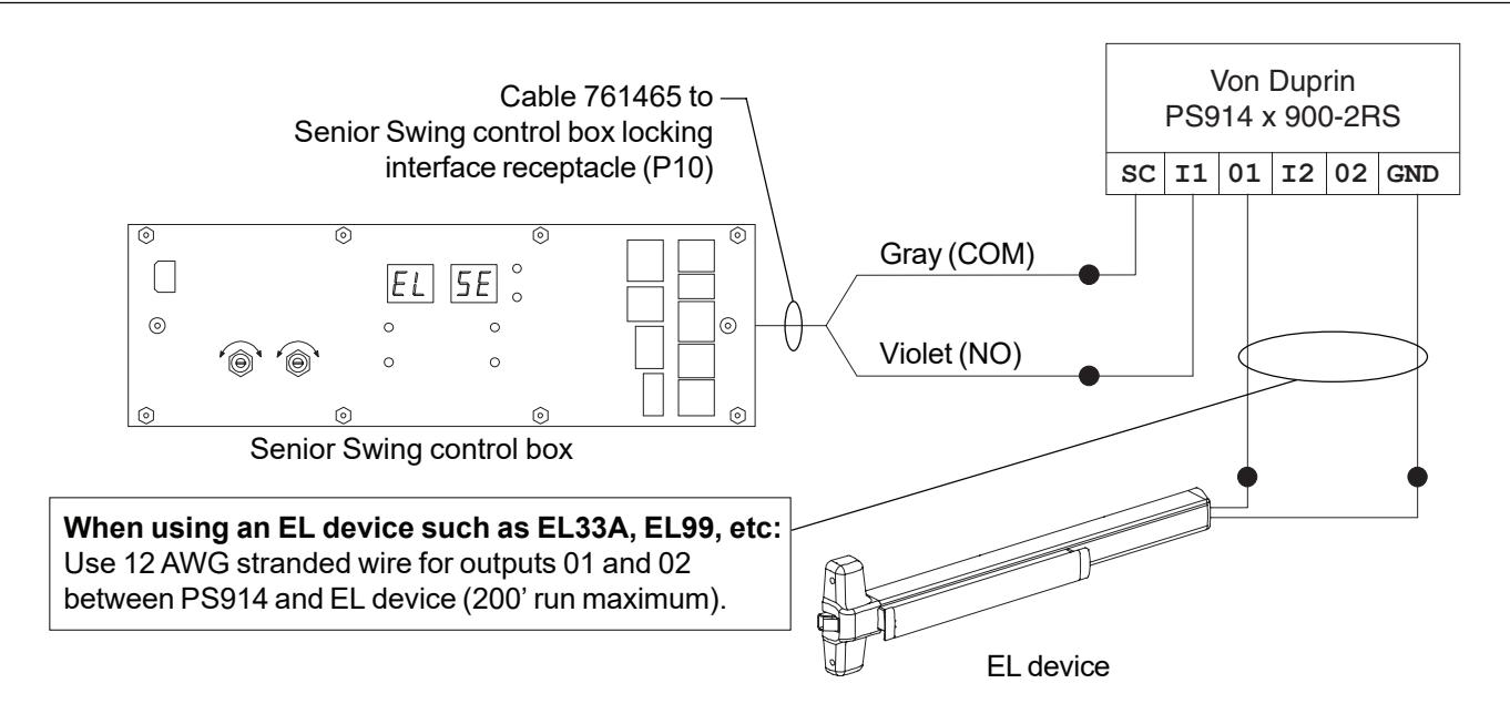
The keypad EL (electric lock) setting is SE (fail secure). The control box locking relay signals the PS914 x 900-2RS. When the operator is on, the EL device is locked when the door is closed and unlocked when the door is opening. When the 3-position switch is set to OFF, the EL device is locked.
Figure 3-7. Sample Wiring for a Fail Secure EL (Electric Latch Retraction) Locking Device
4 Keypad Settings
Settings (except for close speed) for the Senior Swing Power Operator System are changed using keypad pushbuttons and an alphanumeric display on the control box (Figure 4-1 and Figure 4-2). Close speed is changed using dials on the control box (Figure 4-1).
See page 9 and page 10 for directions for changing the values of settings.
A CAUTION A
Adjust the operator for the slowest operation practical in accordance with the latest revisions of Americans with Disabilities Act, ANSI/BHMA A156.19 (American National Standard for Power Assist and Low Energy Power Operated Doors), and local codes.


Figure 4-2. Closeup of Control Box Keypad
WARNING
KEEP HANDS, CLOTHING, WIRES, TOOLS, LADDERS, ETC. AWAY FROM THE DOOR WHEN THE OPERATOR IS INITIALLY TURNED ON.
See Figure 4-3 for definitions of the positions of the door throughout the opening and closing cycle.
See Table 4-1 for explanations of the keypad settings.
To change setting values:
- 1. Set the 3-position switch, if used, to OFF.
- 2. Apply AC power. The POWER light will illuminate and the display will remain blank.
- 3. Press any two pushbuttons at the same time for 1 second to turn on the keypad. The display will illuminate.
- 4. Press the UP or DOWN setting selection pushbutton to select the desired setting. The setting is shown in the SETTING display, and the current value for that setting is shown in the VALUE display.
- 5. Press the UP or DOWN value selection pushbutton to select the desired value for the displayed setting. The value for the setting is indicated in the VALUE display.
- 6. The keypad will automatically turn off after 5 minutes of inactivity.
To reset all values to default (default values are listed in Table 4-1 under "Selectable Values"):
- 1. Set the 3-position switch, if used, to OFF.
- 2. Apply AC power. The POWER light will illuminate, and the display will remain blank.
- 3. Press any two pushbuttons at the same time for 1 second to turn on the keypad. The display will illuminate.
- 4. Press the DEFAULT pushbutton for 4 seconds.
- 5. The values are set to default, and the display will indicate the opening speed setting and value.
- 6. The keypad will automatically turn off after 5 minutes of inactivity.

Safety side Door Mounted Safety Sensor (DMSS) disable feature
Purpose:
Deactivate the Door Mounted Safety Sensor (DMSS) on safety side of door to eliminate nuisance detection of a wall or guard rail.
- 1. Install control box, all door hardware and safety devices per their instructions.
- 2. Setup DMSS sensors in accordance with ANSI standard 156.10.
- 3. Use keypad to set SAFETY SLOW/STOP (SS) value to STOP (SP).
- 4. Use keypad to set SLOWDOWN DISABLE (SD) value to 85.
- 5. Activate door opening cycle. If door does not open fully, use keypad to reduce SD value from 85 in 5 degree increments.
- 6. Repeat Step 5 until door opens fully.
- 7. Perform a complete system test as described in the section 5.

Table 4-1. Control Box Settings and Selectable Values
| Setting | Setting Display | Selectable Values |
Values as
Displayed |
Description |
|---|---|---|---|---|
| Opening Speed |
01 = slow
02 = medium 03 = fast (default = 01) |
Controls opening speed of any normal
weight and size door |
||
| Back Check Speed |
01 = slow
02 = medium (default = 01) |
Controls speed of door near full open
position to prevent door slamming open |
||
| Back Check Position |
45-80 degrees
(default = 70) |
Approximate angle at which door
begins to decelerate near the full open position |
||
| Hold Open Delay |
01-32 seconds
(default = 05) |
Amount of time (in seconds) door
remains fully open following an activate signal |
||
| Latch Position |
00-23 degrees
(default = 13) |
Approximate angle at which door
begins to decelerate near the full closed position |
||
| Auto Reverse Closing |
off, on
(default = off) |
When on, door will re-open upon
hitting an obstruction |
||
| Electric Lock |
off
SA = fail safe SE = fail secure (default = off) |
To turn on, set to SA (fail safe) or SE
(fail secure) to match locking device connected to control box locking interface receptacle (P10); when on, causes a 1 second delay between activate signal and door opening to allow time for most electric locks to disengage before operator opens door |
||
| Power Boost |
off
1 sec 2 sec 3 sec 4 sec 5 sec continuous |
When on, increases closing force of
door from 9 lbs to 18 lbs to close door against high winds or stack pressure; turns on for seconds or continuously after door reaches latch position during closing cycle; disabled by Power Boost disable input |
||
| Push 'N' Go |
off, on, fd
(default = off) |
When set to On or Fd, pushing door
open 5 degrees causes operator to open door remainder of way and hold open. Hold open time is same as hd setting when set to On. Hold open time is 1 second when set to Fd. |
||
| Alternate Activate |
off, on
(default = off) |
When on, door stays open until a
second activate signal is received. |
||
| Safety Slow/Stop |
slow, stop
(default = slow) |
Determines response to a DMSS on
the safety side of the door; if SL (slow), door goes to back check speed; if SP (stop), door stops for 5 seconds, then continues opening at back check speed |
||
| Special |
off
30-85 (default = off) |
Deactivate the Door Mounted Safety
Sensor (DMSS) on safety side of door to eliminate nuisance detection of a wall or guard rail. |
||
| Status Announcement | Reserved | Reserved | Reserved |
WARNING
KEEP HANDS, CLOTHING, WIRES, TOOLS, LADDERS, ETC. AWAY FROM THE DOOR WHEN THE OPERATOR IS INITIALLY TURNED ON.
If control box does not operate as expected during system test, see section 6 for troubleshooting tips.
- 5a With the door closed, set the 3-position switch, if used, to AUTO and turn on all AC power. For applications using companion door, try to get both doors to open same amount of degrees before hitting hard stop (either internal gearbox stop or rubber bumper on wall).
- 5b Activate the operator using an activation device. The operator should perform one sizing cycle.
Sizing cycle: Occurs when the door is activated for the first time after power is turned on. During the sizing cycle, the door opens and closes once.
If the door sizes properly, go to step No. 5.3.
If the door does not open at all during the sizing cycle:
- Check that the 3-position switch, if used, is not set to OFF.
- Check door for binds and proper mechanical installation.
- Verify that all safety sensors are inactive.
- If an electromechanical lock is used, check that the lock disengages before the operator opens the door.
- Verify that the Breakaway switch, if used, is connected to NC contacts. If a Breakaway switch is not used, check that the Breakaway cable coming from the control box logic board is jumpered (jumper part No. 761492-00).
- Check fuse, wiring, and connections.
- Adjust the operator as follows and check door operation:
Opening speed: ..........................01 Back check speed: ......................01 for slow, 02 for medium Hold open delay: .........................05 Back check position: ...................75 Latch position: .............................10 Close speed: ...............................medium Electric lock: ................................SA (fail safe) or SE (fail secure) to match lock
If the door does not open fully during the sizing cycle, check door for binds, obstructions, or items that could activate safety sensors.
- 5c After the sizing cycle is complete and the door is closed, apply a maintained activation signal and check that the door remains open while the activation signal is applied. Then release the activate signal and verify door closes after the open time delay expires.
- 5d To check the function of the door safety device:
- 1. Activate the door and then activate the approach side safety device while the door is open. The door should not close while the safety device is activated. Next, deactivate the safety device. The door should close after the hold open time delay expires.
- 2. With the door closed, activate the safety side safety device, then activate the door. The door should not open while the safety device is activated. Next, deactivate the safety device. The door should open when activated.
- 5e Set the 3-position switch, if used, to HOLD. Verify that the door opens and stays open.
- 5f Set the 3-position switch, if used, to OFF. Verify that the door closes. Verify that an activate signal does not open the door.
- 5g If a Breakaway switch is connected, set the 3-position switch, if used, to AUTO, then break open the door. Verify that an activate signal does not cause the door to move. Re-latch the door after testing.
- 5h Do not release the system for service until it is operating properly.
6 Troubleshooting
- 6a Identify all switch and sensor inputs that are currently active:
- 1. Remove breakaway jumper to enter diagnostic mode.
- L Note: When in diagnostic mode, controller will not open door.
- 2. Keypad display shows each active input signal for 1 second. See table below:
| (Key switch) set to Auto OR is not presentSA80 | |
|---|---|
| (Key switch) set to OFFSA81 | |
| (Key switch) set to HOLDSA82 | |
| (Activate) input is ONSA83 | |
| (DMSS approach) activate input is ONSA84 | |
| (DMSS safety) slowdown input is ONSA85 | |
| (Carpet Safety) input is ONSA86 | |
| (Bodyguard) input is ONSA87 | |
| (Power Boost Disable) input is ONSA88 |
For example, if key switch is set to Auto, Activate button is pressed, and DMSS sees something on the safety side, then display will repeat the sequence SA80, SA83, SA85 continuously until breakaway jumper is replaced.
- 3. After completing diagnostics, reinstall breakaway jumper for normal operation.
-
6b If control box does not function and the error message Er## flashes on the control box Setting and Value displays, turn AC power off and on to reset the control box. The following are common errors and suggested fixes:
- ER 06: Master motor problem verify master motor cable is connected to motor.
- ER 14: Companion door added to a setup that was already sized turn AC power off, then on and resize with both doors connected.
If problem cannot be corrected by using suggested fixes, contact 1-877-671-7011.
7 Release for Service
- 7a Remove all tools, installation equipment, and debris from the vicinity of the door.
- 7b Install all safety, traffic control, and instruction decals on the door as required by the latest revision of ANSI/BHMA A156.19. This is very important! Failure to do this leaves the installer LIABLE for any accident that might occur. This must be done!
- 7c Verbally instruct the owner or person in charge of the proper operation of the door.
- 7d Instruct the owner or person in charge to routinely inspect the door for the following:
- Visible damage
- Developing problems
- Minor preventive maintenance
- 7e Instruct the owner or person in charge who and where to call for service when required.
IMPORTANT
Make sure to install all safety, traffic control, and instruction decals on the door as required.
