LCN_2310ME-420_Sentronic_Installation_Instructions_111111
Open the original PDF document
View PDF

18766
2310ME-420 Sentronic
LCN ®
Installation Instructions
If closer has optional hold-open bypass feature, bypass label will be on cylinder.
A CAUTION A
Improper installation or regulation may result in personal injury or property damage. Follow all instructions carefully. For questions, call LCN at 877 - 671 - 7011
1 Installation
Closer handed at factory and must match hand of door.
2
Voltage shown on box label must match voltage supplied to door frame.
3
If door & frame are not prepared for closer & track, prepare according to details on opposite side.
4
- a. Cut soffit from frame.
- b. Assemble flexible conduit connector to conduit mounting bracket.
- Connect input voltage to plug leads as shown in wiring diagram in Step 10.
- d. Insert closer into frame and secure with proper screws.
- e. Replace soffit.
5
Insert track roller into track. Insert track and fire shield in door cut out and secure with proper screws.
6
Place arm on closer shaft and secure with shaft screw.
7
Loosen set screw in end of arm, open door part way (about 30°), pull arm over top of door and connect to track roller. Tighten set screw firmly.

Customer Service 1-877-671-7011 www.allegion.com/us
8
Regulation: Do not allow door to slam into frame. A "normal" closing time from 90° open position is 5 to 7 seconds. Use a 3/32"
hex wrench. To slow MAIN SPEED of door, turn regulation screw (nearest arm) clockwise. To slow LATCH SPEED of door, turn regulating screw (nearest latch) clockwise.
Backcheck: To increase BACKCHECK, turn regulating screw (nearest hinge) clockwise. Using lightest BACKCHECK that will retard door opening sufficiently.

DO NOT USE AN ABRUPT BACKCHECK NOR EXPECT DOOR CLOSER TO ACT AS DOOR STOP.
9 Closing Power
Adjust CLOSING POWER only if more power is needed. Closer is shipped with minimum closing power pre-set. To increase CLOSING POWER turn spring adjusting screw clockwise. Maximum adjustment of 18 turns.

10 Electrical Checkout
a. With power on, open the door any position and release. The
door should remain in the hold-open position within 10°. For a bypass model to hold open, the door must be opened beyond degree of door swing indicated on label.
chassis ground
Input Voltage 12V AC/DC 24V AC/DC or 120V AC/DC (Usually from Alarm Panel or Detector)
Wiring Diagram
- b. If not, push on/off switch.
- If door does not stay open, verify electrical input in wiring diagram at right.
- d. Turn power off, door should close completely.
- e. To release hold open manually, pull door firmly. Door should close completely under power of closer.
- f. System should be checked at regular intervals. It is suggested that steps A & D be repeated every 90 days.
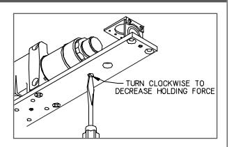
11 Holding Force Adjustment
IF DOOR IS HARD TO PULL OUT OF HOLD OPEN, ADJUST AS SHOWN.
Holding Force is at maximum. This can be decreased and increased again but not increased beyond original setting.

© Allegion 2015 Printed in U.S.A. 18766 Rev. 10/15-c


| Additional Notes: | |
|---|---|
| 1. None | |
| Revision History | Revision Description: | |||||||||
|---|---|---|---|---|---|---|---|---|---|---|
| J | K | L | М | N | Р | C > Revised artwork | ||||
| 043228 | ] | |||||||||
| Material | Edited By | Approved By | EC Number | Release Date | ||||||
| White Paper | J. Ellis | J. Pattar | xxxxxx | 10-14-15 | ||||||
| Notes | Title | |||||||||
|
2310ME-420 Instruction Sheet | |||||||||
| 3. tolerance ± .13 | Creation Date | Number | Revision | |||||||
|
05-10-10 | 18766 | C | |||||||
| 3. drawin |
Created By
N/A |
Activity
3899 Hancock Expwy |
||||||||
| Software: InDesign CS6 | Security, CO 80911 | © Allegion 2015 | ||||||||