LCN SEM 7840 and SEM 7850 Series IS 109737
Open the original PDF document
View PDFSEM 7840/7850
Installation Instructions
29352 Sentronic Electro-Magnetic Single Door Holder Concealed Wall Mount
CAUTION
Improper Installation may result in personal injury or property damage. Follow all instructions carefully. For questions, call LCN at 877-671-7011
1 Locate the Junction Box (Not Provided)
- 1a See Fig. 1. Measure dimensions A and B. Find the intersection of those two dimensions in Table 1. The intersection is dimension C, the centerline of the surface mount box location. (For 180 ° installations, take B dimension and subtract 5 ⁵⁄₈" to fi nd the centerline of junction box.
- Note: Optional extensions may be needed.
- 1b If dimension A or B is not shown on the chart, extrapolate to fi nd dimension C as follows:
- If dimension A is 11" and dimension B is 36", then: Dimension C = 33 - ((33-32 ¹⁄₂)/2)= 32 ³⁄₄
- If dimension A is 12" and dimension B is 35", then: Dimension C = 32 ¹⁄₂ - ((32 ¹⁄₂ - 30 ³⁄₈)/2)= 31 ⁷⁄₁₆
- If dimension A or B is beyond those listed in Table 1 or if they intersect in a blank area in Table 1, use optional extensions as needed to align contact plate and magnet.
- 1c See Fig. 2. The center of the junction box should be located about 5" from the top of the door. Install junction box to withstand at least a 50 pound pull.
- 1d Pull wire in accordance with applicable codes, standards, and authorities having jurisdiction. Electrical specifi cations are shown below.
| Input Voltage | Current Draw Max. | ||||
|---|---|---|---|---|---|
| 120VAC, 60Hz | .02A | ||||
| 24VAC, 60Hz/24VDC | .02A | ||||
| 12VDC | .03A | ||||
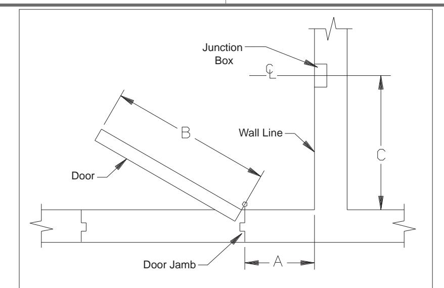
Figure 1
2 Install the Magnet
- 2a The magnet is shipped partially assembled for protection. Unscrew the cover from the magnet bracket assembly. Keep the screws for later reattachment.
- 2b See Fig. 3. Connect the supply earth ground wire to the green wire on the magnet bracket assembly. Connect the power supply common wire to the screw terminal marked COM. If the supply voltage is 24V, connect the power supply hot wire to the screw terminal marked 24V. If the supply voltage is 12V, connect the power supply hot wire to the screw terminal marked 12V. Polarity is important on the 12V input. There are protective plastic tabs over the terminal screws. Break off the two tabs that protect COM and the desired voltage so that the screw heads are exposed.
- 2c See Fig. 2. With the magnet wired, position the magnet bracket assembly into the junction box and attach it to the box using the (2) 6-32 screws. Tighten fi rmly. Attach the cover housing using the (2) 10-24 screws from step 2A.
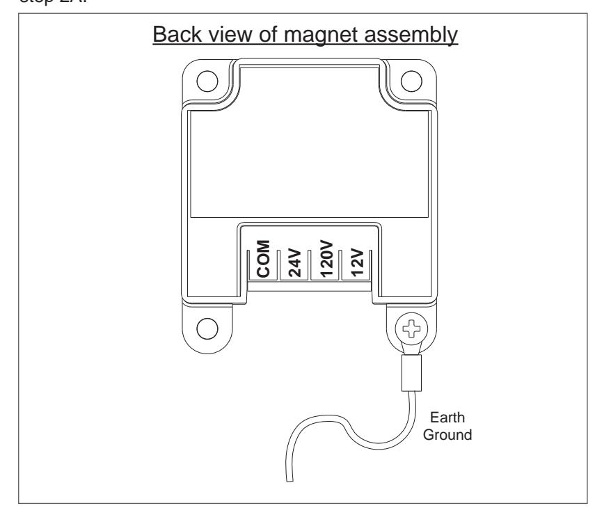
Figure 3
|
Magnetic Door Holder Placement Chart+
7840/50 |
||||||||||||
|---|---|---|---|---|---|---|---|---|---|---|---|---|
| B= dimension of door width (Inch) | ||||||||||||
|
Nearest Whole
Number |
28 | 30 | 32 | 34 | 36 | 38 | 40 | 42 | 44 | 46 | 48 | |
| A = Dimension of door jamb to wall (Inch) | 2 | 26 ¹⁄₈ | 28 ¹⁄₈ | 30 ¹⁄₈ | 32 ¹⁄₈ | 34 ¹⁄₈ | 36 ¹⁄₈ | 38 ¹⁄₈ | 40 ¹⁄₈ | 42 ¹⁄₈ | 44 ¹⁄₈ | 46 ¹⁄₈ |
| 4 | 26 | 28 | 30 | 32 | 34 | 36 | 38 | 40 | 42 | 44 | 46 | |
| 6 | 25 ³⁄₄ | 27 ³⁄₄ | 29 ¹³⁄₁₆ | 31 ¹³⁄₁₆ | 33 ¹³⁄₁₆ | 35 ⁵⁄₈ | 37 ⁷⁄₈ | 39 ⁷⁄₈ | 41 ⁷⁄₈ | 44 | 46 | |
| 8 | 25 ⁵⁄₁₆ | 27 ³⁄₈ | 29 ⁷⁄₁₆ | 31 ¹⁄₂ | 33 ¹⁄₂ | 35 ¹⁄₂ | 37 ⁵⁄₈ | 39 ⁵⁄₈ | 41 ⁵⁄₈ | 43 ⁵⁄₈ | 45 ¹¹⁄₁₆ | |
| 10 | 24 ³⁄₄ | 26 ¹³⁄₁₆ | 29 | 31 | 33 | 35 ¹⁄₈ | 37 ³⁄₁₆ | 39 ¹⁄₄ | 41 ¹⁄₄ | 43 ⁵⁄₁₆ | 45 ³⁄₈ | |
| 12 | 24 | 26 | 28 ¹⁄₄ | 30 ³⁄₈ | 32 ¹⁄₂ | 34 ⁹⁄₁₆ |
36 ¹¹
₁₆ |
38 ³⁄₄ | 40 ¹³⁄₁₆ | 42 ⁷⁄₈ | 45 | |
| 14 | 23 | 25 ³⁄₁₆ | 27 ³⁄₈ | 29 ⁵⁄₈ | 31 ³⁄₄ | 33 ¹⁵⁄₁₆ | 36 | 38 ¹⁄₈ | 40 ¹⁄₄ | 42 ⁵⁄₁₆ | 44 ³⁄₈ | |
| 16 | 21 ⁵⁄₈ | 24 | 26 ³⁄₈ | 28 ⁵⁄₈ | 30 ⁷⁄₈ | 33 | 35 ¹⁄₄ | 37 ⁷⁄₁₆ | 39 ⁹⁄₁₆ | 41 ¹¹⁄₁₆ | 43 ¹³⁄₁₆ | |
| 18 | 20 ¹⁄₈ | 22 ³⁄₄ | 25 ¹⁄₈ | 27 ¹⁄₂ | 29 ¹³⁄₁₆ | 32 ¹⁄₈ | 34 ³⁄₈ | 36 ⁹⁄₁₆ | 38 ³⁄₄ | 41 | 43 | |
| 20 | 18 ¹⁄₄ | 21 | 23 ¹¹⁄₁₆ | 26 ³⁄₁₆ | 28 ⁵⁄₈ | 31 | 33 ⁵⁄₁₆ | 35 ⁹⁄₁₆ | 37 ¹³⁄₁₆ | 40 | 42 ¹⁄₄ | |
| 22 | 19 | 22 | 24 ⁵⁄₈ | 27 ³⁄₁₆ |
29 ¹¹
₁₆ |
32 | 34 ⁷⁄₁₆ | 36 ³⁄₄ | 39 | 41 ⁵⁄₁₆ | ||
| 24 | 22 ³⁄₄ | 25 ¹⁄₂ | 28 ¹⁄₈ | 30 ¹¹⁄₁₆ | 33 ¹⁄₈ | 35 ³⁄₁₆ | 38 | 40 ¹⁄₄ | ||||
| 26 | 26 ³⁄₈ | 29 | 31 ¹¹⁄₁₆ | 34 ⁵⁄₈ | 36 ⁵⁄₈ | 39 | ||||||
| 28 | 30 | 32 ⁵⁄₈ | 35 ³⁄₁₆ | 37 ¹¹⁄₁₆ | ||||||||
| 30 | 28 | 30 ⁷⁄₈ | 33 ⁹⁄₁₆ | 36 ³⁄₁₆ | ||||||||
| 32 | 31 ¹¹⁄₁₆ | 34 ¹⁄₂ | ||||||||||
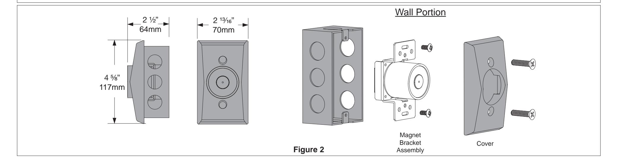
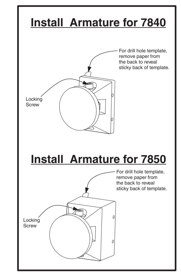
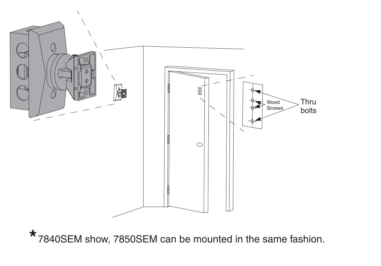
Figure 4
3 Install the Door Armature
- 3a See Fig. 4. Slightly loosen the contact plate locking screw using a 5/32" Allen wrench so the contact plate can rotate with some resistance. Remove the protective paper from the drill template sticky-back label on the back of the door armature.
- 3b Place the armature against the wall magnet. This is best done with power applied to the magnet. If power is not available, hold the armature in place by hand. The armature contact plate must fully cover the magnet. If the contact plate is not centered and flat on the magnet, reduced holding force will result.
- With the armature against the magnet, open the door and press it against the armature and magnet. Pull the door away to transfer the drill template to the door. Template may need assistance with transferring to door, using a flat blade screwdriver on the template tab that sticks out and push it onto the door while pulling the door away.
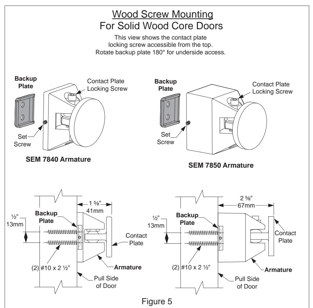
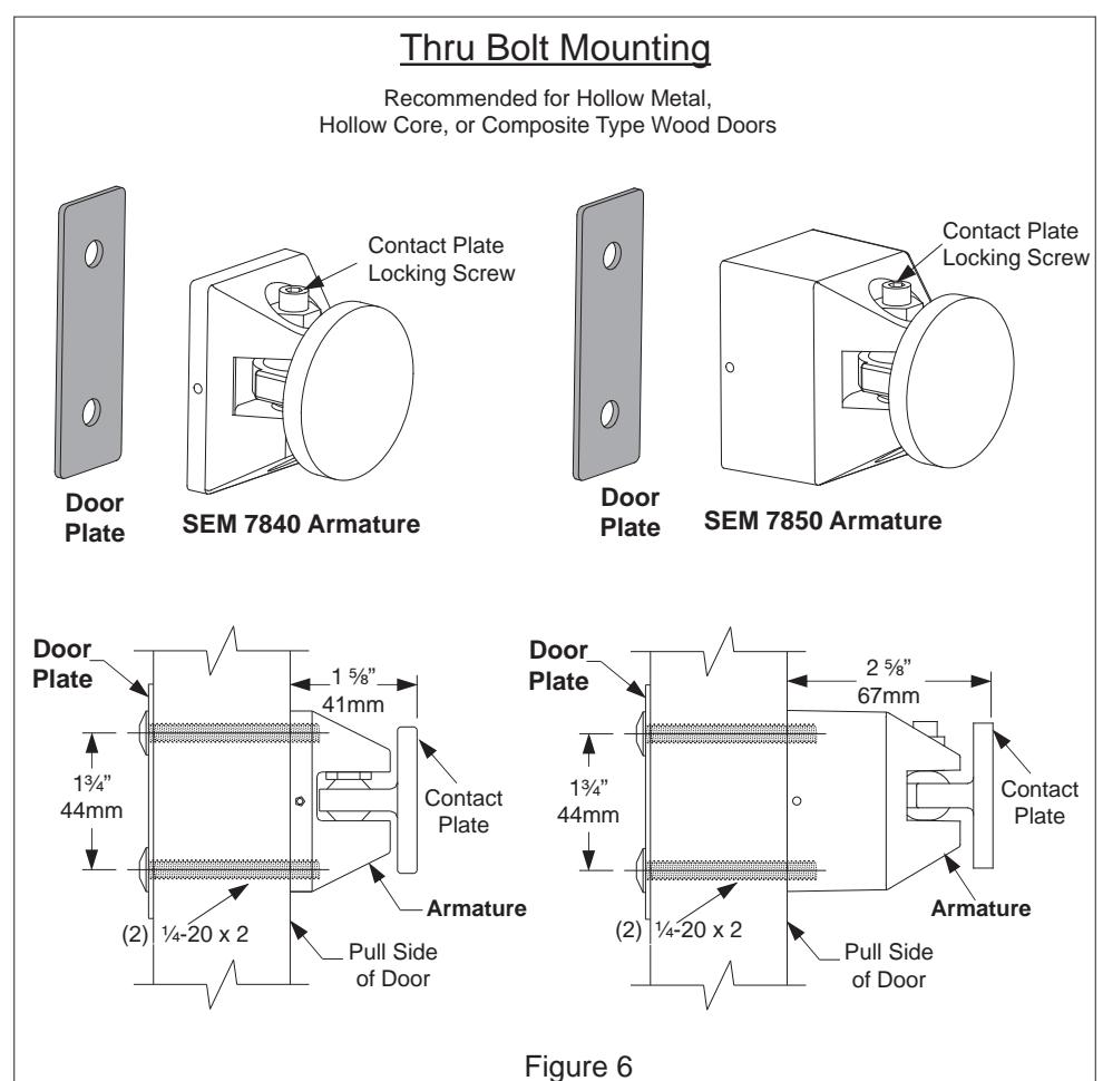
- See Fig. 5 and 6. Determine if the armature will be mounted using the wood screw kit or the thru bolt kit. The thru bolt kit is recommended for 1 ¾" hollow metal, hollow core, or composite-type wood doors. If using the wood screw kit, drill the center two holes on the template using a ¾" bit by 1 ¼" deep. If using the thru bolt kit, drill the outer two holes on the template using a 5/16" bit all the way through the door. Remove the template after the holes are drilled.
- 3e Attach the armature to the door using the appropriate plate and screws. If using the wood screws and backup plate, tighten the armature set screw against the backup plate as the last step using the 1/16" Allen wrench provided.