LCN SEM 7820 Series Installation Instructions 109735
Open the original PDF document
View PDF

SEM 7820
Sentronic® Electro-Magnetic Single Door Holder Floor Mounted

SINGLE DOOR INSTALLATION
Step 1: Plan the Installation
- A. Measure the door width.
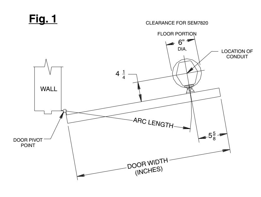
- B. Calculate the arc length by subtracting 5 5/8" from the door width. Draw an arc at the calculated length using the door pivot point as the center point. String and a pencil could be used to draw the arc on the floor.
- C. Open the door to the desired position. On the pull side of the door, put a mark on the arc 4 1/4" from the door. This is the center of the conduit hole.
- D. Drill and install conduit as needed. Maximum conduit size is ½". Maximum conduit height above the floor is 1".
- E. Pull wire in accordance with applicable codes, standards, and authorities having jurisdiction. Electrical specifications are shown below.
| Input Voltage | Current Draw Max. |
|---|---|
| 120VAC, 60Hz | .02A |
| 24VAC, 60Hz/24VDC | .02A |
| 12VDC | .03A |

Step 2: Install the Magnet
- A. The magnet is shipped partially assembled for protection. Unscrew the cover from the base, then unscrew the magnet bracket assembly from the base. Keep the screws for later reattachment.
- B. Guide the conduit through the hole in the base and snug up the conduit nut. Square up the base to the door, with the door opened to the desired position, as shown in Fig.1.
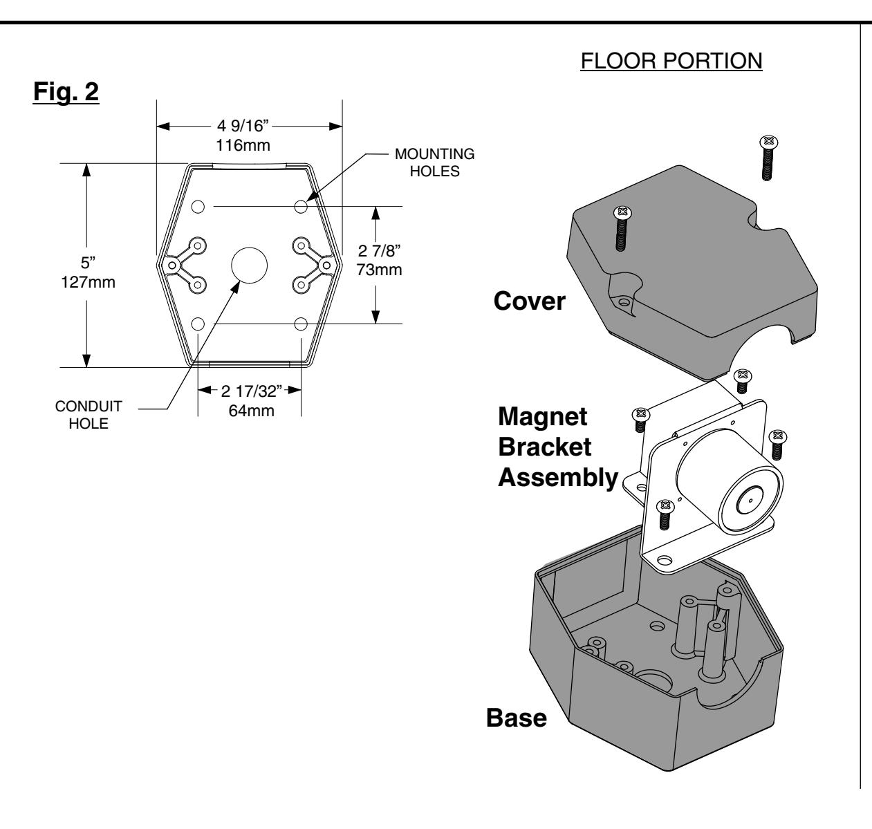
- C. See Fig. 2. Using the base as a template, mark the four mounting hole locations on the floor.
- D. Remove the base and drill 3/8" holes in the floor at 1 1/4" deep. Install the cement anchors provided into the drilled holes, threaded ends up.
- E. Reposition the base, aligning the mounting holes with the floor holes and the magnet opening facing the door. Tighten the conduit nut. Install (2) 1/4-20 mounting screws that are furthest away from the magnet opening into the cement anchors. The magnet assembly must first be connected to power supply wires before the other two base housing mounting screws can be installed.
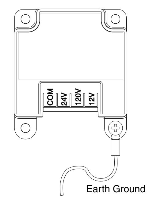
- F. See Fig. 3. Connect the supply earth ground wire to the green wire on the magnet assembly bracket. Connect the power supply common wire to the screw terminal marked COM. If the supply voltage is 24V, connect the power supply hot wire to the screw terminal marked 24V. If the supply voltage is 120V, connect the power supply hot wire to the screw terminal marked 120V. If the supply voltage is 12V, connect the power supply hot wire to the screw terminal marked 12V. Polarity is important on the 12V input. There are protective plastic tabs over the terminal screws. Break off the two tabs that protect COM and the desired voltage so that the screw heads are exposed.
- G. See Fig. 2. With the magnet wired, position the magnet bracket assembly over the two base mounting holes and the two base post holes. Insert (2) 1/4-20 base mounting screws into the cement anchors and the (2) 10-24 shorter screws from step 2A into the post holes. Tighten firmly. Attach the cover using the (2) 10-24 longer screws from step 2A.
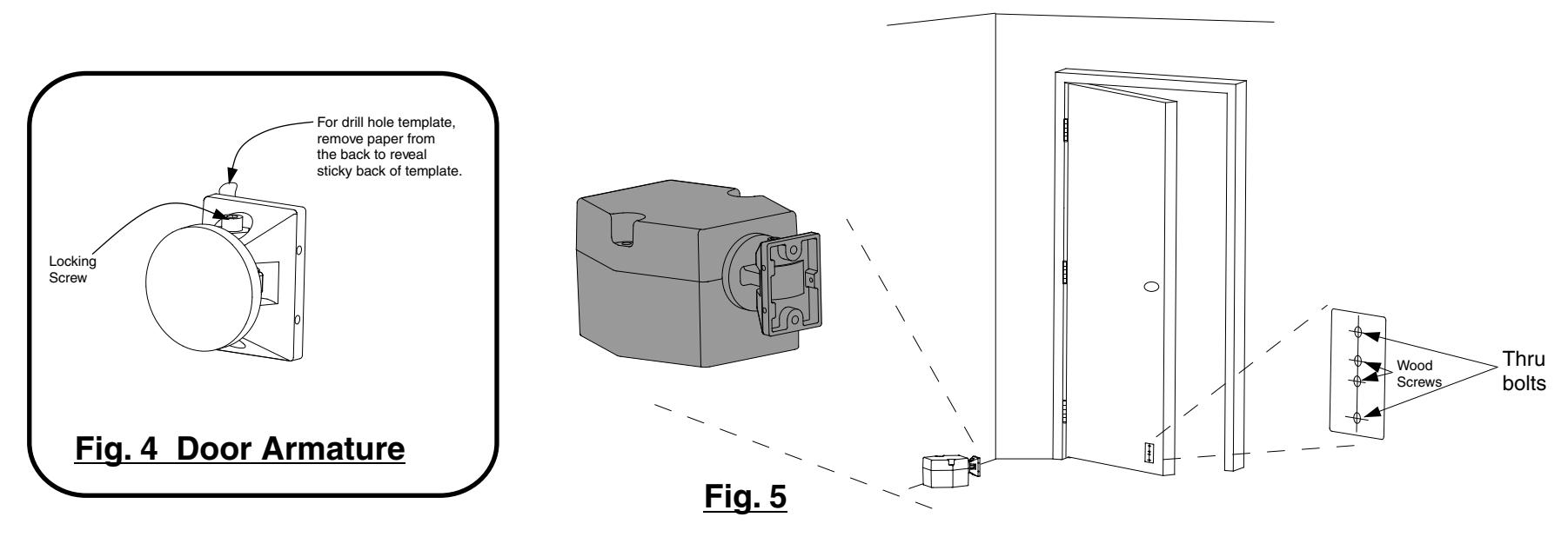
Step 3: Install the Door Armature
- A. See Fig. 4. Slightly loosen the contact plate locking screw using a 5/32" Allen wrench so the contact plate can rotate with some resistance. Remove the protective paper from the drill template sticky-back label on the back of the door armature.
- B. See Fig. 5. Place the armature against the floor magnet. This is best done with power applied to the magnet. If power is not available, hold the armature in place by hand. The armature contact plate must fully cover the magnet. If the contact plate is not centered and flat on the magnet, reduced holding force will result.
- C. With the armature against the magnet, open the door and press it against the armature and magnet. Pull the door away to transfer the drill template to the door. Template may need assistance with transferring to door, using a flat blade screwdriver on the template tab that sticks out and push it onto the door while pulling the door away.
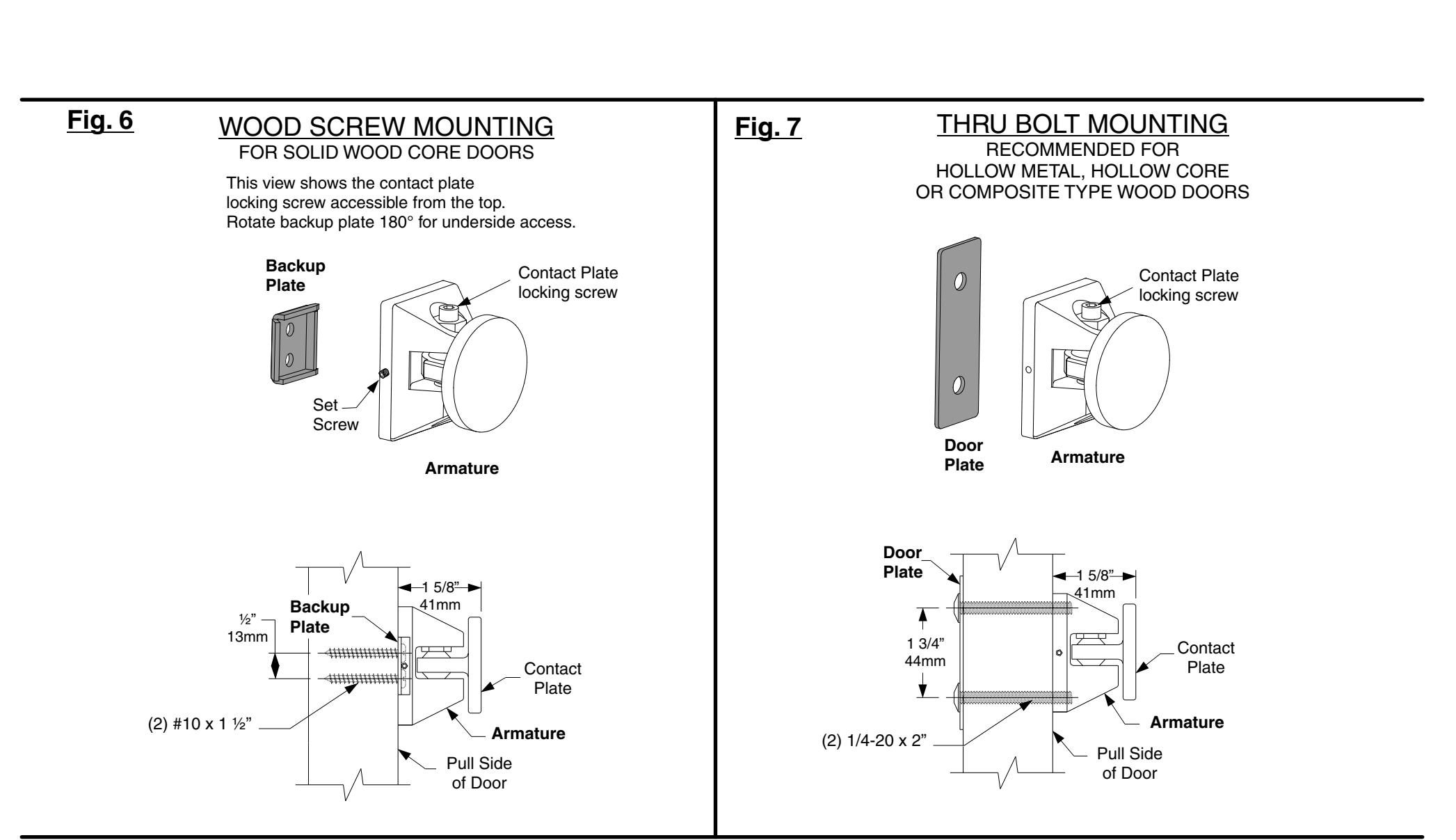
- D. See Fig. 6 and 7. Determine if the armature will be mounted using the wood screw kit or the thru bolt kit. The thru bolt kit is recommended for 1 ¾" hollow metal, hollow core, or composite-type wood doors. If using the wood screw kit, drill the center two holes on the template using a 1/8" bit by 1 ¼" deep. If using the thru bolt kit, drill the outer two holes on the template using a 5/16" bit all the way through the door. Remove the template after the holes are drilled.
- E. Attach the armature to the door using the appropriate plate and screws. If using the wood screws and backup plate, tighten the armature set screw against the backup plate as the last step using the 1/16" Allen wrench provided.