LCN ES7982 Series SEQ Installation Instructions 107032
Open the original PDF document
View PDF
23656
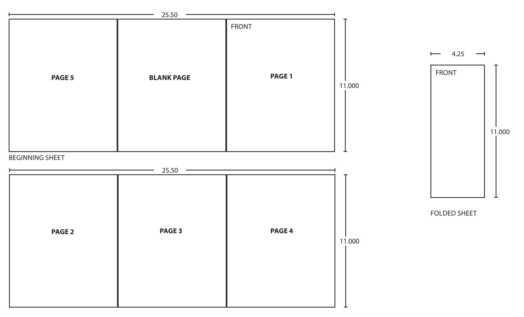
Model ES7982 SEQ

Control Box Installation Instructions
For closer information see closer installation instruction sheet.
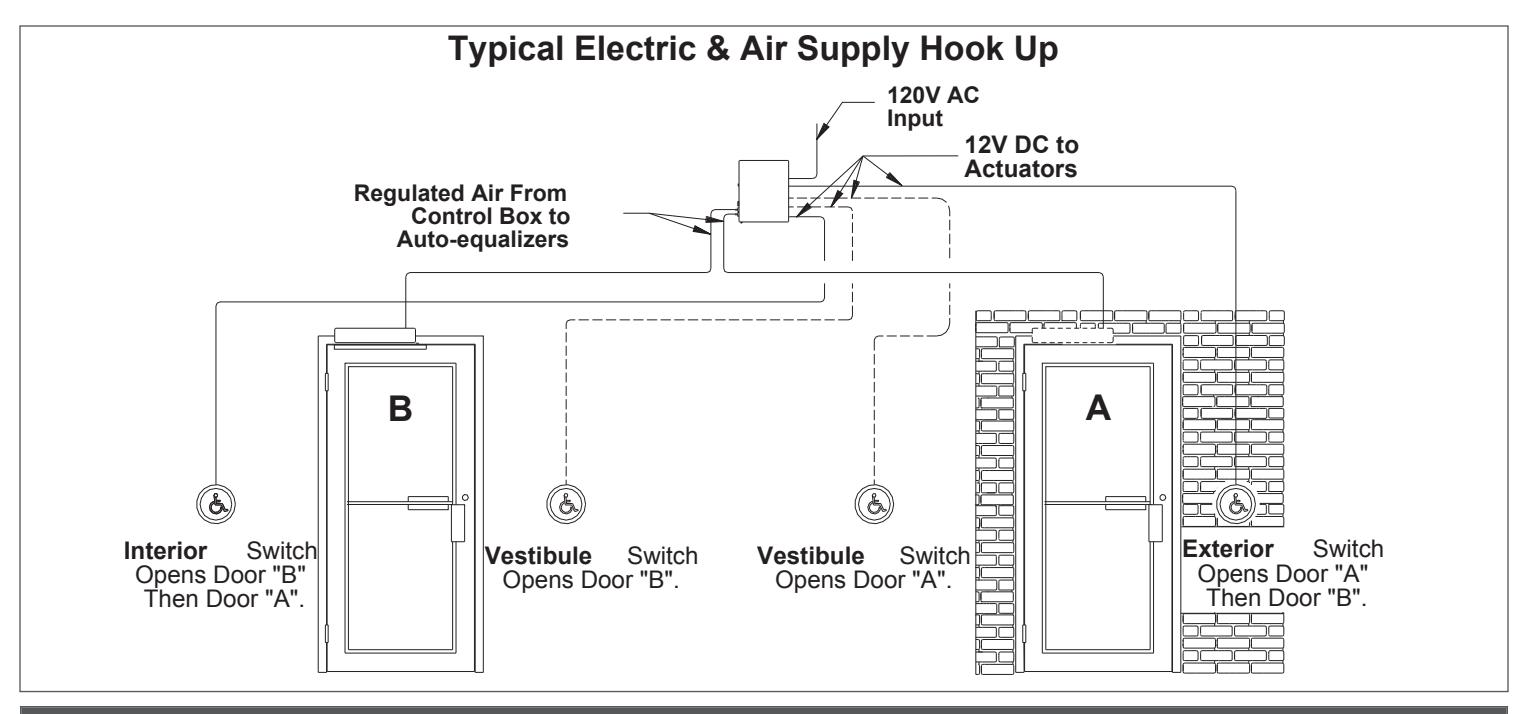
Installation
- 1a Locate box on interior of building within 50 tubing feet of the farthest door to be controlled. Box must be in a clean, dry, well ventilated place where temperatures do not exceed 120°F or fall below 35°F.
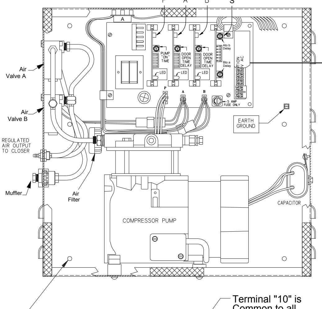
- 1b Mount box to a structurally sound surface using screws provided as shown on page 2 with air fittings on left side as shown. Box must be in a clean, dry, well ventilated place where temperatures do not exceed 120°F or fall below 35°F.
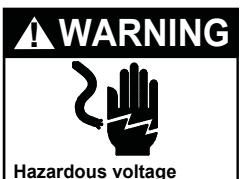
- 1c Refer to instructions packed with actuators and connect leads to terminals 5 through 10 as required.
- 1d Connect unpowered 120V AC input to terminals 3, 4, and ground screw. (Line side to terminal 3, neutral side to terminal 4 and ground wire to ground screw.) If door control is on a fire door, 120V AC input must be interrupted by the fire alarm panel when in alarm. When dry auxiliary fire alarm contacts are used, remove shunt from terminals 1 and 2 and connect to dry contacts of fire detector or alarm panel. Terminals 1 and 2 are in series with line side of 120V input.
- 1e Turn on power. Air valves and compressor will operate one cycle when power is applied.
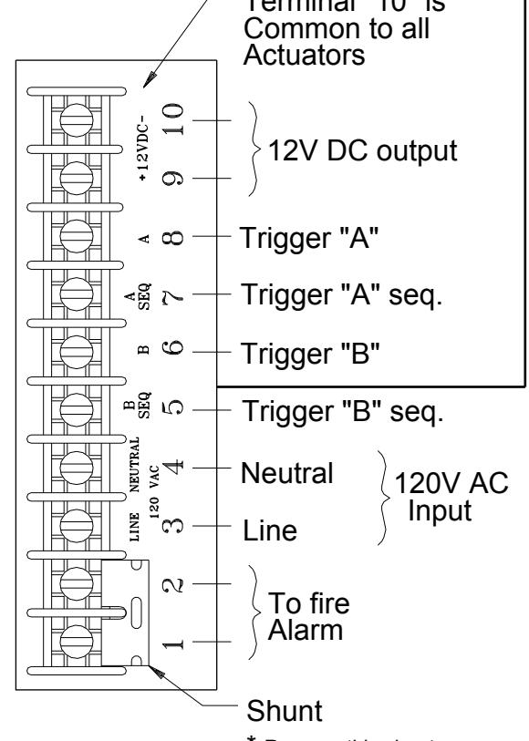
- 1f Air pressure output has been preset at factory. If more air pressure is required to adequately open doors, regulate air adjustment valve on pump, as shown on page 3 .
- 1g Adjust time delay to keep air valve energized by turning adjustment wheel on timer modules "A" & "B" (CW to increase - CCW to decrease). The LED (light) on the timer module indicates the valve is energized. The time can be adjusted from 0-30 seconds. 10 seconds is a "normal" delay.
- L NOTICE: Timer Module "A" and "B" must operate longer than Timer Module "P".
- 1h Adjust timer module "P" to keep compressor activated for the necessary amount of time to open the door. This can be done by rotating the adjusting wheel. (CW to increase - CCW to decrease). The LED (light) on the timer module indicates the compressor is energized. The compressor should not run more than 1-3 seconds longer than the time required to open the door.
- 1i When using sequential operation, adjust dual timer module "S" for desired delay between door operation. (CW to increase delay; CCW to decrease delay). Top timer delays "A" to "B" operation; the bottom timer delays "B" to "A" operation.
- 1j Test actuators to insure wiring and tubing are properly connected.
ACAUTION
Do not mount box upside Down or in horizontal Position. Locate where Temperatures do not Exceed 120°F or fall Below 35°F
ACAUTION
Components inside control Box will be hot to touch Under normal operation. Allow box to cool down Before making adjustments.
Can shock and Cause severe injury
Disconnect power before Making any electrical Connections or performing Maintenance.
Air filter should be Inspected every six Months.If filter is Damaged,contact Icn For replacement.
Install box with six tapcon
Drill 5/32 hole 1 1/4 deep
With carbide tipped
Concrete drill bit
Concrete screws 3/16 x 1 1/4
Electrical Data
Input = 120V AC @ 5 amps Power consumption 600watts Output is 12v dc (250 ma max.Load)
A DANGER
Control box MUST be connected to earth ground
* Remove this shunt Only when connecting To normally closed Fire alarms contacts
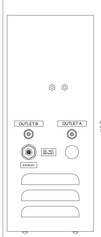
Air Pressure Adjustment
- 1a Loosen lock nut.(A)
- 1b Turn outer valve (B) to regulate air pressure.
- 1c Tighten lock nut.
Installation Troubleshooting Chart
| Symptom | Possible Cause | Suggested Remedy | |||
|---|---|---|---|---|---|
| No Power Opening | No power to control box / blown fuse |
Verify 120VAC 60HZ power is present
at terminals 3 & 4 on control box terminal strip. Check fuse. Replace only with 5 amp (3AG type) fuse. |
|||
| Actuator(s) not connected properly |
Be sure a timer module board is
firmly in place in "A". "B" & "P" slots. Timer card "S" must be in place for sequential operation. Operate actuator(s). LED on timer module should light when actuator is used. The LED on timer "P" should light whenever "A" or "B" is lit. If not, momentarily short actuator terminals 6 & 10 and 8 & 10 in the control box. If LED lights, check wiring to actuators for an open circuit. If it does not light, check for voltage at terminals 9 & 10. Voltage should read from 11.75 to 13.25V DC. If there is no reading, disconnect leads from terminals 9 & 10. Short actuator terminals 6 & 10 and 8 & 10. If LED lights, check for short circuit in actuators. |
||||
|
Fire alarm system causing open
circuit on terminals 1 & 2 |
Shunt terminals 1 & 2 with power off.
Restore power. If control operates when actuator terminals in the control box are shorted, an open circuit exist in wiring to fire alarm. When Auto Equalizer is not used with fire alarms, terminals 1 & 2 must be permanently shorted with a shunt. IMPORTANT! When Auto-Equalizer is connected to fire alarm, make sure shunt is removed from terminals 1 & 2. Terminals 1 & 2 are one leg of |
||||
| No input to Auto-Equalizer operator |
120V line.
Disconnect tubing from Auto Equalizer operator. Try actuator and verify that air is coming out of tubing. If not, trace tubing to control box, checking for breaks or kinks in air line. |
||||
| Air lines obstructed with dirt or ice. |
Clean or thaw lines and reroute if
necessary. Eliminate dips near cold zones. |
||||
|
Air valves not working
Compressor not working |
Make sure air valve leads are
plugged into main board. (Be sure valves in system are plugged into connectors "A" & "B".) Make sure compressor leads are plugged into main board. (Be sure |
||||
|
compressor is plugged into connector
"P"). |
|||||
| Symptom | Possible Cause | Suggested Remedy | ||
|---|---|---|---|---|
| Does not open or fully open | Control box exhaust restricted. |
Exhaust muffler may be clogged by
dirty air or accidental painting. Clean in alcohol or mineral spirits. |
||
| Opens too slow or not at all | Inlet filter clogged |
Replace filter element (Contact LCN
for replacement) |
||
| Power opening will not time out. |
Scanner maintaining signal to control
box. |
Make sure lenses are clean and
there are no obstructions in front of scanner. Adjust range as described in scanner instructions. |
||
| Switch circuit maintaining contact. |
Check for short circuit or error in
wiring to switch or scanner. |
|||
|
Air valve blocked open with
contaminant. |
Cycle valve several times by
momentarily shorting actuators in the control box. This should clear valve. |
|||
| Power opening timing out too soon. | Air compressor needs readjustment. |
See page 3 for regulation
instructions. |
||
| Timer cards not set properly |
Set timer cards "A" & "B" for Max.
time. Set timer card "P" for Min. time. Slowly increase card "P" until "time out" is 1-3 seconds after door is fully open. Decrease timer card "A" & "B" to achieve desired time delay before closing. (Make sure "P" times out before "A" & "B".) |
|||
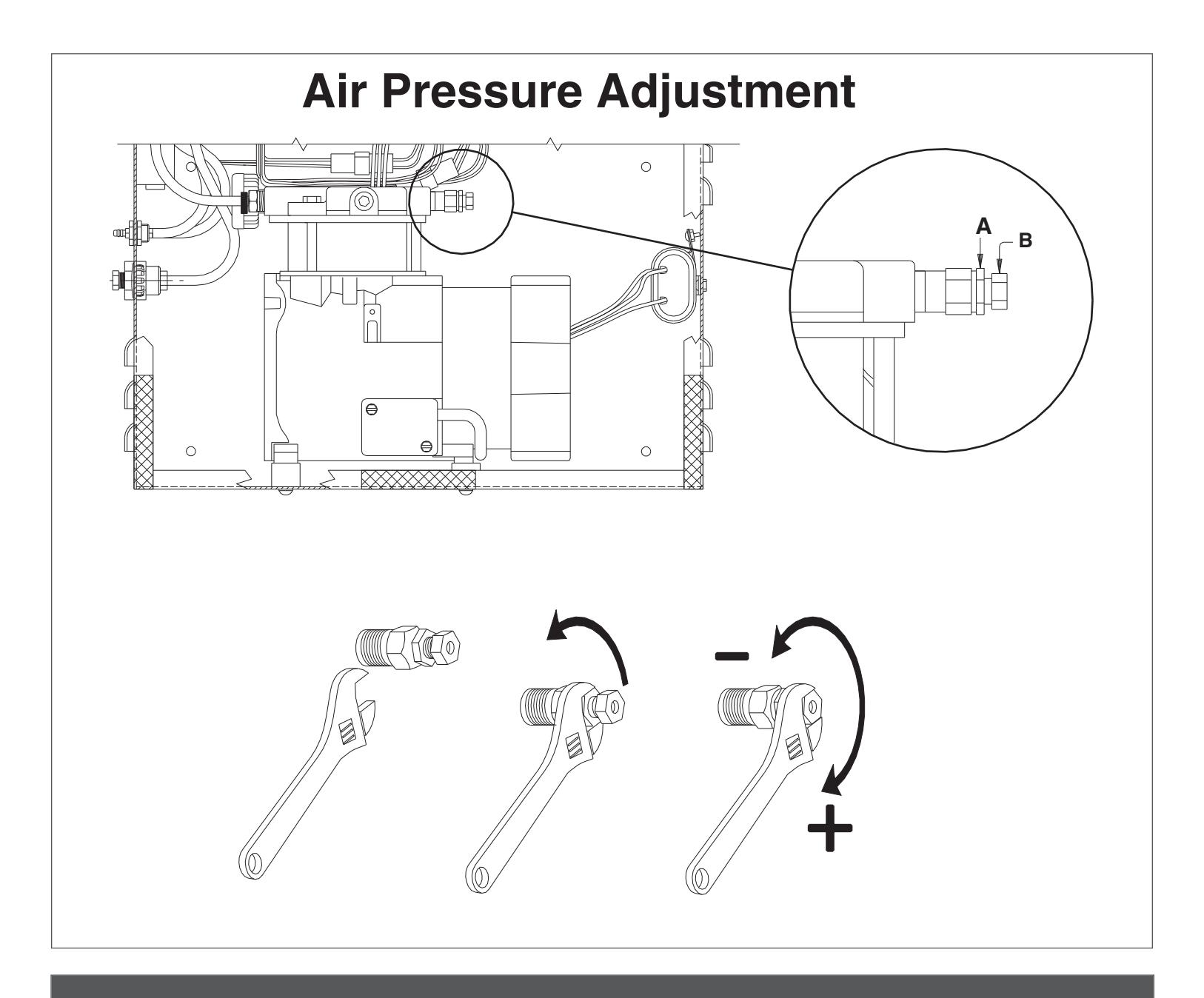
MODEL ES7982 SEQ FOR USE WITH ELECTRIC LATCHING HARDWARE
ES7982 SEQ - 2 electric strikes maximum
! WARNING
HAZARDOUS VOLTAGE CAN SHOCK AND CAUSE SEVERE INJURY
Disconnect power before making any electrical connections or performing maintenance.
VIOLET / WHITE - VIOLET WIRE N.O. FAIL SECURE STRIKE (N.O. CONTACT)
Strike releases when energized. Remains locked in alarm or power failure. (Manual release hardware required to open door in alarm or power failure.)
BROWN / WHITE - BROWN WIRE N.C.
Strike releases with alarm or power failure. Remains lached with power on. (Not compatible with UL listed fire door.)


| Additional Notes: | Revision History | Revision Description: | ||||||||
|---|---|---|---|---|---|---|---|---|---|---|
| 1. None | E | E F G H J K | E > Revised artwork | |||||||
| 043228 | ] | |||||||||
| Material | Material White Paper | Edited By | Approved By | EC Number | Release Date | |||||
| D. Myers | M. Sasso | 043228 | 01-01-14 | |||||||
| 1 1 . | Notes 1. printed two sides 2. printed black | Title ES7982 Series Sequential Control Box Instruction Sheet | ||||||||
|
3. toleran
4. printed |
|
Creation Date
01-02-13 |
Number 23656 |
Revision
E |
||||||
| 5. drawin | 5. drawings not to scale |
Created By
N/A |
Activity
3899 Hancock Expwy |
|||||||
| Software: InDesign CS6 | Security, CO 80911 | © Allegion 201 | ||||||||
Release Date
© Allegion 2014