LCN 7980 Series Compressor Service Kit Installation Instructions 107147
Open the original PDF document
View PDF

7980 Series

Compressor Service Kit
Installation Instructions
1
Remove damaged hardware from location indicated in Fig. 1 . Remove adjusting screw, lock nut, spring and button assembly. To remove steel ball lightly tap on air adjustment valve.
2
Replace hardware with the new hardware that is provided in service package shown in Fig. 2. Assemble hardware into air adjustment valve in order that is shown in Fig. 2 , starting with steel ball and ending with the adjustable screw.
3
To regulate outer valve air pressure see Fig. 3 on the back page.
Caution
Do not mount box upside down or in horizontal position. Locate where temperatures do not exceed 120°f or fall below 35°f.
warning

HAZARDOUS VOLTAGE CAN SHOCK AND CAUSE SEVERE INJURY
Disconnect power before making any electrical connections or performing maintenance.
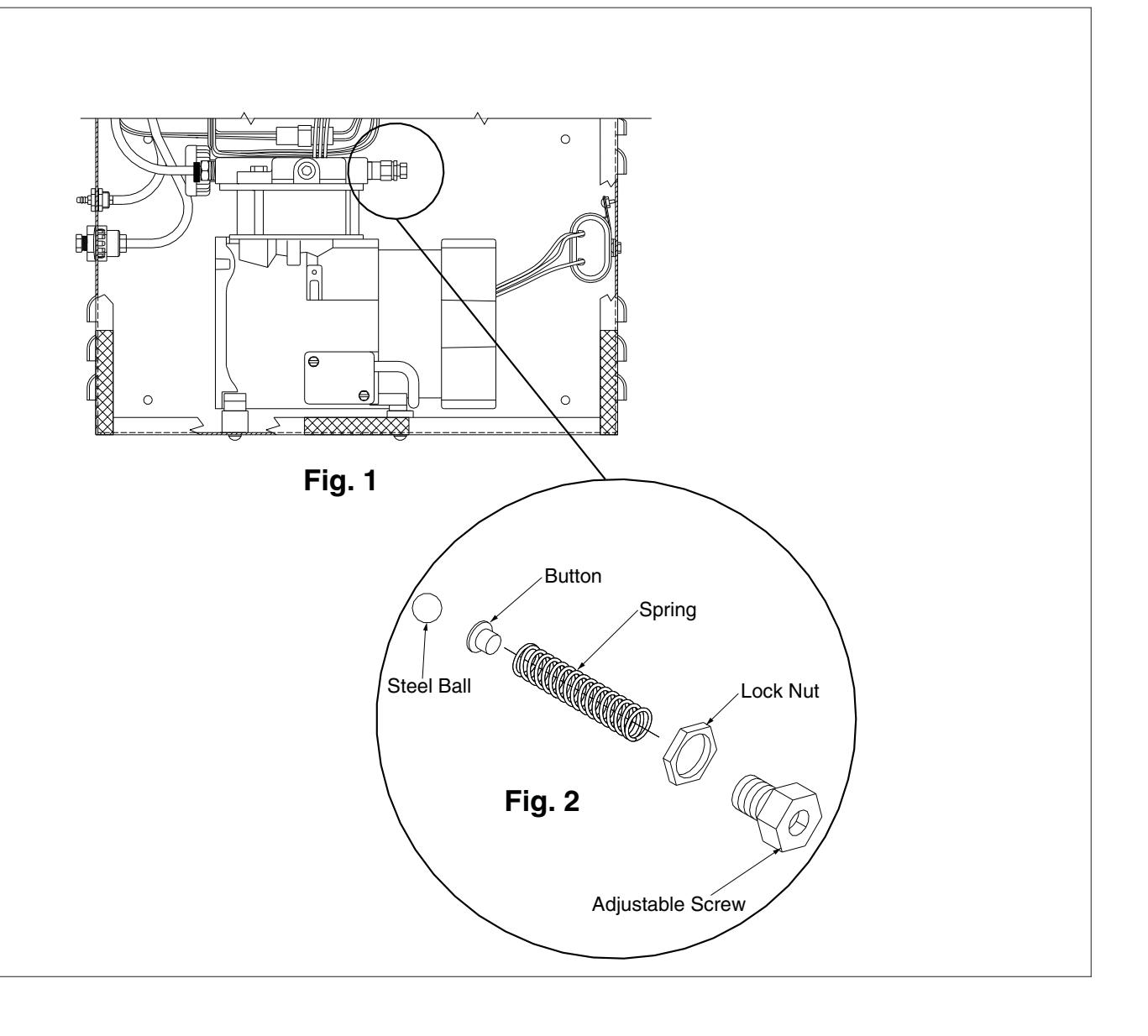
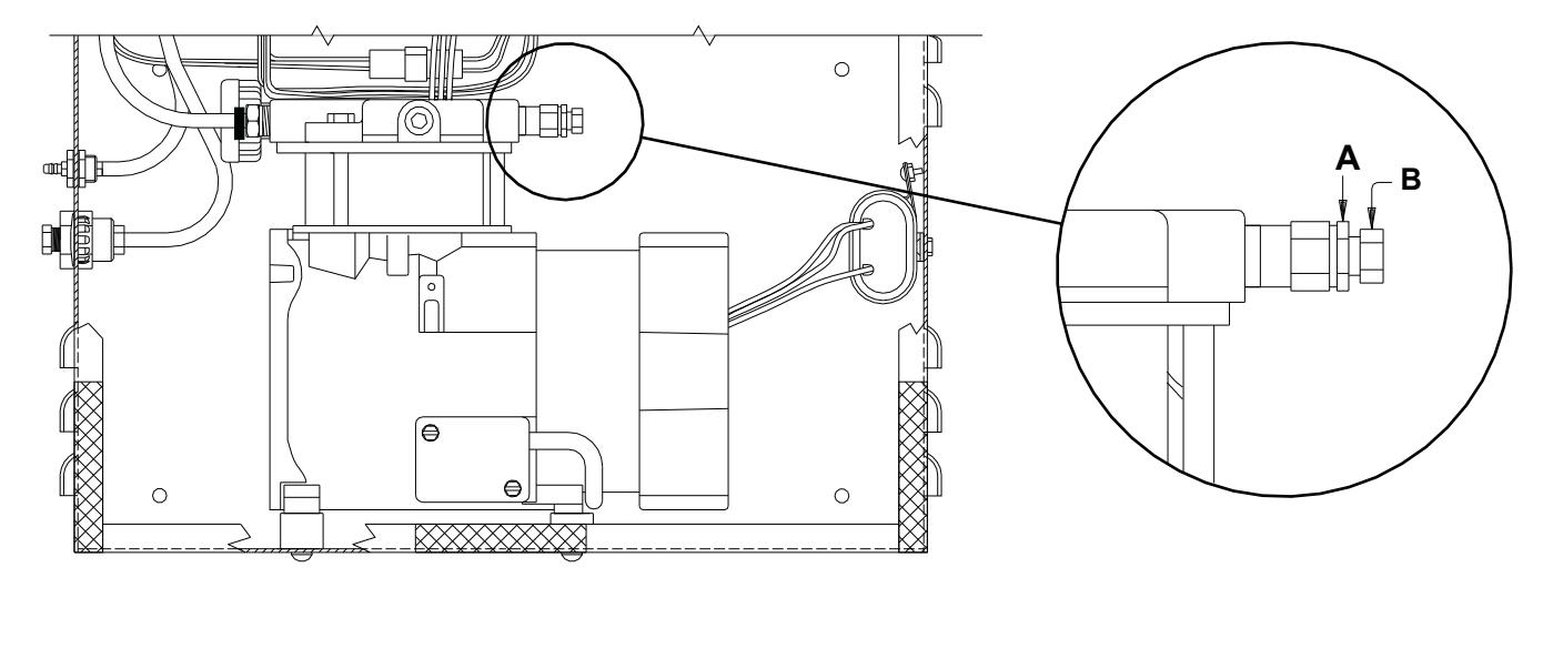
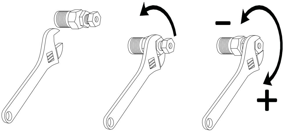
Fig. 3 Air Pressure Regulation
1
Loosen lock nut. (A)
2
Outer valve (B) regulates the air pressure to the cylinder. Adjust outer valve (B) in quarter turn increments until door properly opens. DO NOT over adjust - compressor will be damaged. When the door fully opens there should be air exhausting from the vent hole in (B) before the compressor shuts off, if the valve is properly adjusted.
3
Tighten lock nut.

FINAL SHEET
BEGINNING SHEET
| Additional Notes: | |
|---|---|
| 1. None | |
| Revision History | Revision Description: | |||||||||
|---|---|---|---|---|---|---|---|---|---|---|
| Α | В | С | D | Е | F | C > Revised artwork | ||||
| N/A | N/A | 043812 | ] | |||||||
| Material White Paper | Edited By | Approved By | EC Number | Release Date | ||||||
| D. Myers | M. Sasso | 043812 | 01-01-14 | |||||||
| Notes 1. printed two sides 2. printed black 3. tolerance ± .13 4. printed in country may vary 5. drawings not to scale | 7980 Series Compressor Service Kit Instruction Sheet | |||||||||
|
Creation Date
04-27-10 |
Number 26941 |
Revision
C |
||||||||
|
Created By
N/A |
Activity
3899 Hancock Expwy Security, CO 80911 |
|||||||||
| Software: InDesign CS6 | Allegion 2014 | |||||||||