LCN 7949 ES7949 Series Installation Instructions 106939
Open the original PDF document
View PDF

Model 7949/ES 7949

Blow-Open Control Box Installation Instructions
For Auto-Equalizer & Regular Control Box information, see installation instruction sheets packed with those products.
L NOTE: The 7949 blow open control box is designed to assist in smoke evacuation from fire alarm systems with a normally closed dry contact output. Blow open installations are not listed under section GVEV of the UL Building Materials Directory . The 7949 blow open control boxes are assembled with UL recognized components, it should NOT be used on fire rated doors as described in GVEV of the UL Building Materials Directory .
System Function
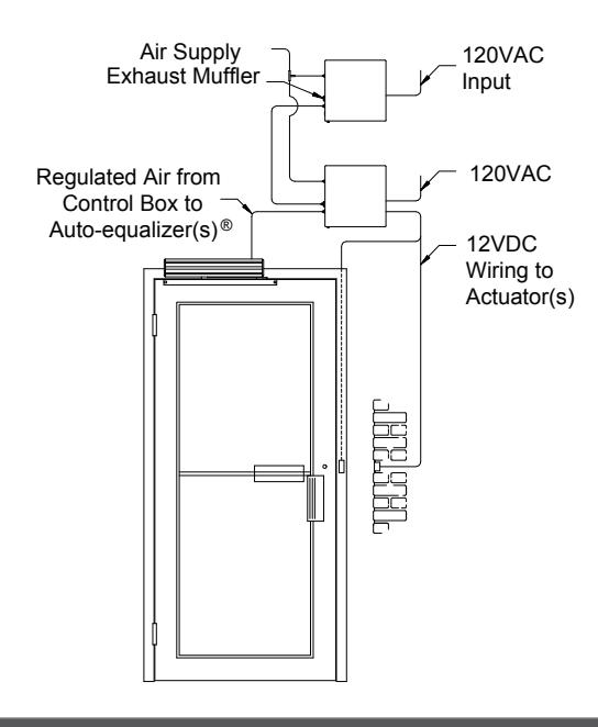
The 7949 series Blow-Open Box is designed for work witha 7901 or 7902 series closer control box and one or more LCN Auto-Equalizer(s) door closer. When power supply to the unit is interrupted by a smoke evacuation system, the 7949 Blow-Open Box overrides the closer control box, opening door(s) with the Auto-Equalizer(s) to allow fresh air into the building. This system is NOT to be used on fire rated doors.
Installing the Blow-Open Box
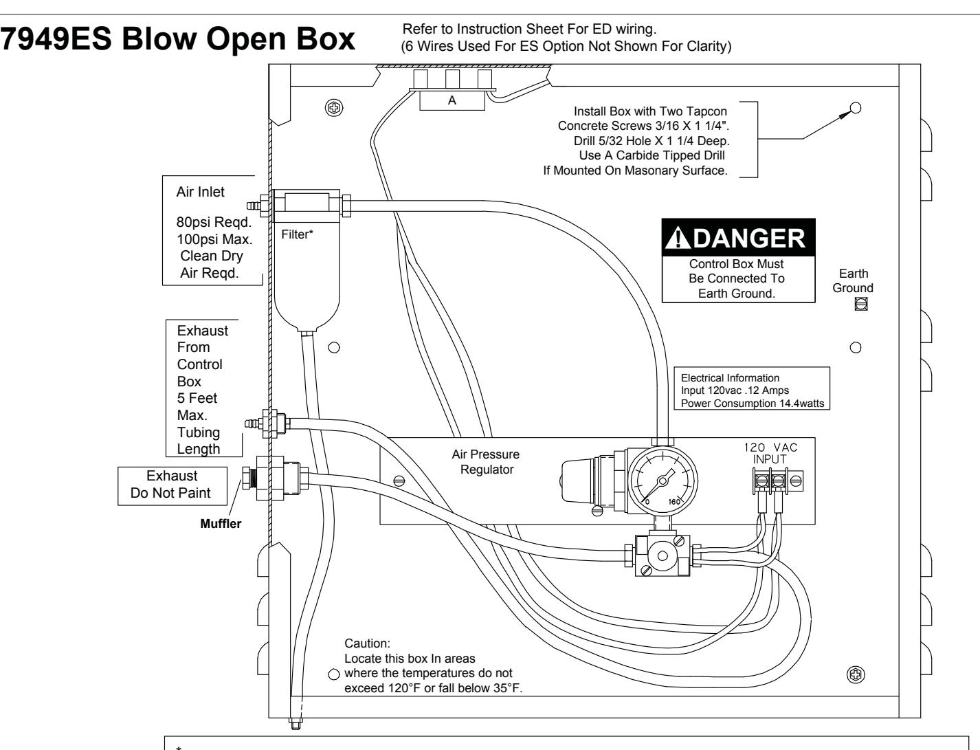
- 1. Locate box within 5 feet of 7900 series control box. It must be mounted in a clean, dry place where temperatures do not exceed 120°F or fall below 35°F.
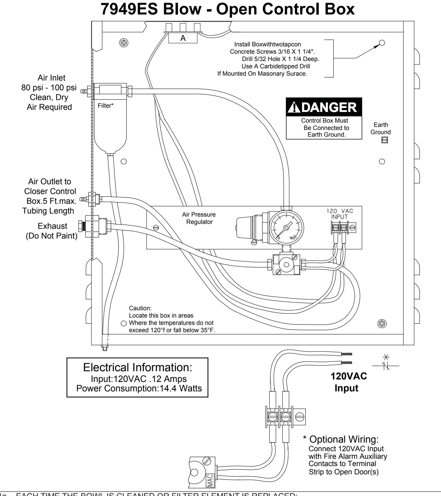
- 2. Mount box to a structurally sound surface using screws provided, with air fittings on left side, as shown on page 4. Do not mount box upside down or horizontally.
- 3. Refer to closer control box instructions and actuator switch instructions. Connect switch leads to proper terminals in the closer control box at this time.
- 4. Connect all air lines to both boxes per required installation (see page 2 for options).
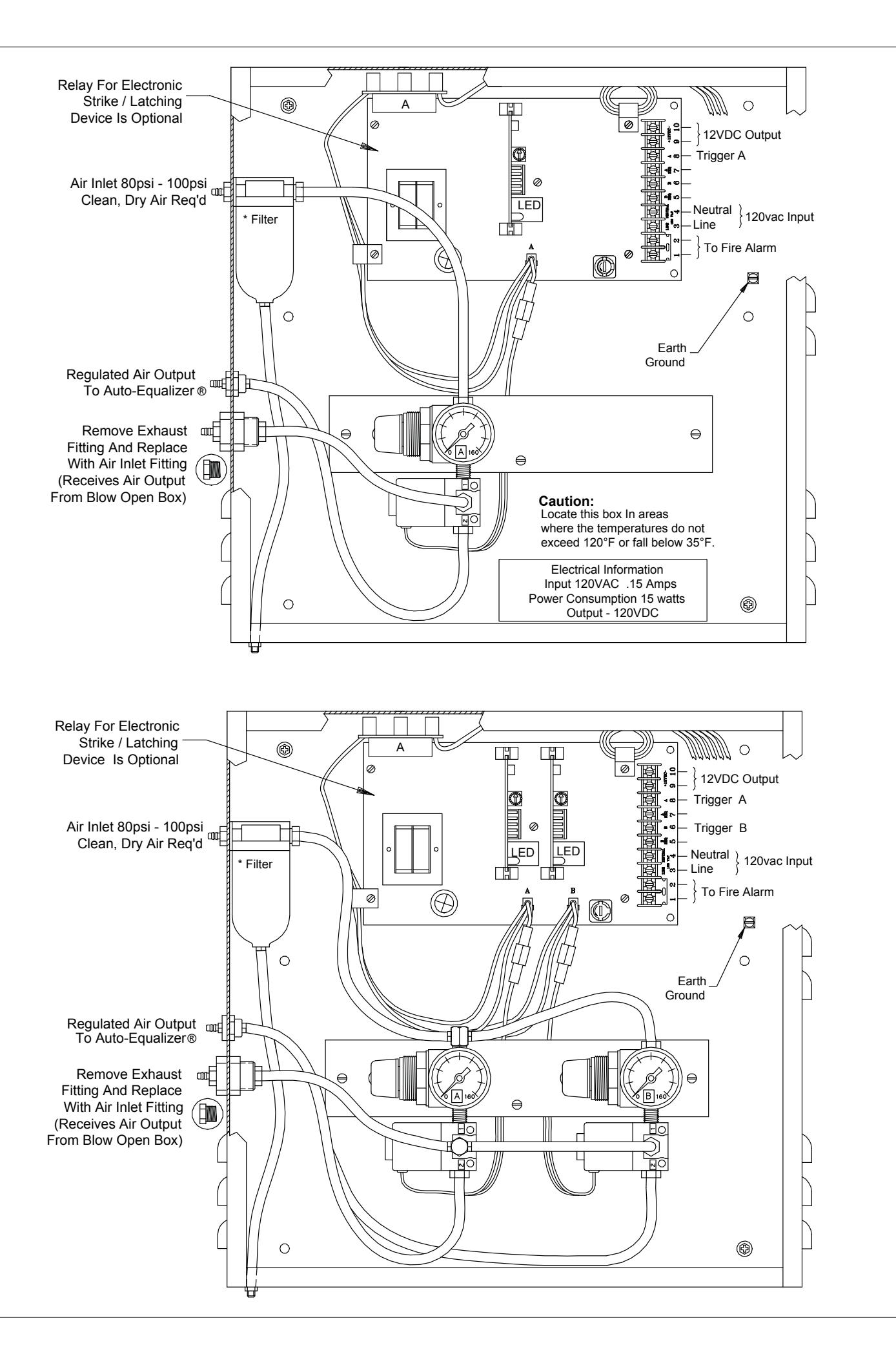
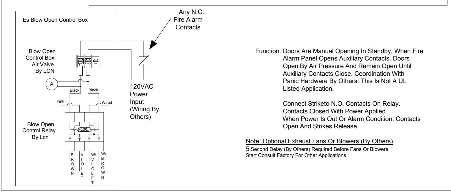
- 5. Connect non-powered 120 VAC line to terminals located in Blow-Open Control Box. If an electronic strikes or latching devices are being used, refer to teh ES7949 box diagram.
- 6. Turn on power to both boxes. Valves will cycle once when power is applied. After cycle is complete, turn on air supply to both boxes.
- 7. Set air pressure at 80 psi in both boxes. Turn regulator knob clockwise to increase pressure, counter-clockwise to decrease pressure. Cycle once with manual override and readjust air pressure if necessary.
- 8. Test actuator switches to ensure wiring and tubing are properly connected.
- L System Note: A minimum five second delay (by others) is required BEFORE smoke evacuation blowers start to allow doors to sufficiently begin to open.

-
1a EACH TIME THE BOWL IS CLEANED OR FILTER ELEMENT IS REPLACED:
- 1. Depressurize unit
- 2. Inspect seals and replace cracked, damaged or deteriorated seals with original manufacturers approved seals only.
- 1b FILTER ELEMNT Clean periodically by removing filter, tapping on a hard surface & blowing off with pressurized air.
- 1c AUTOMATIC DRAIN If drain fails to keep bowl sufficiently free of water, use a small screwdriver to push the piston up, allowing bowl to drain.
- 1d Be sure bowl is securely reinstalled before putting the unit back into service.
- 1e Replacement filters can be ordered from LCN.
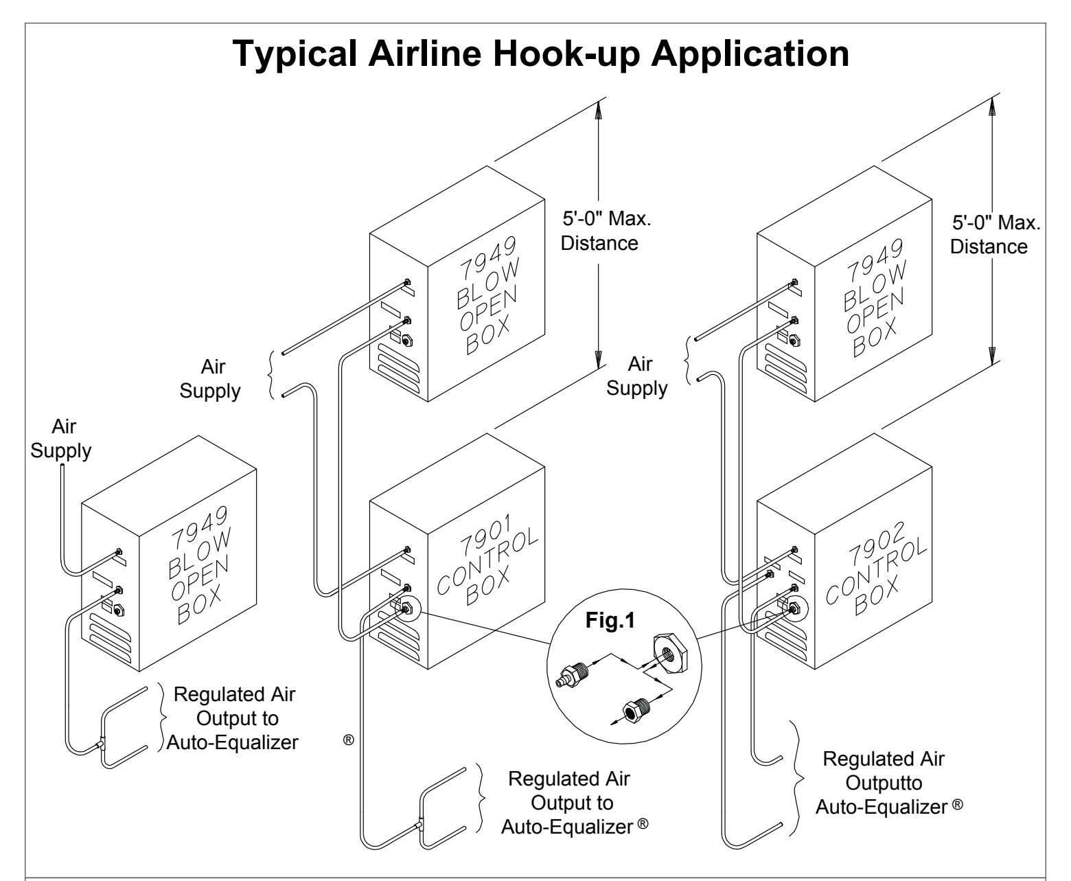
- 1a Connect 1/8" I.D. tubing from air source (providing 80psi to 100psi of clean, dry air) to air inlet fittings located on the side of both the control box & blow-open box.
- 1b Removed exhaust muffler from 7901/ ES 7901 or 7902/ ES 7902 control box and install auxiliary air inlet fitting from hardware package shipped with blow-open box. See Fig. 1.
- L NOTE: when blow-open box is being used independently, connect 1/8" I.D. tubing from air outlet of blow-open box directly to Auto-Equalizer®.
- 1c Connect 1/8" I.D. tubing from "exhaust" fitting on side of control box to outlet "A" fitting on the blow-open box.
- 1d Connect 1/8" I.D. tubing from outlet fitting "A" and/or fitting "B" of the control box to corresponding Auto-Equalizer® unit.
- Filter Maintenance *
-
1. Each Time Bowl Is Cleaned Or The Filter Element Replaced:
- A. Depressurize Unit.
- B. Inspect Seals And Replace Crazed, Cracked, Damaged Or Deteriorated Seals With Original Manufacturer's Approved Seals Only.
- 2. Filter Element -clean Periodically By Removing Filter, Tapping On Hard Surface And Blowing Off With Are Blow Gun.when Cleaning Or Replacing Element, Blow Off Louvers With Air Blow Gun.
- 3. Automatic Drain Models- If Automatic Drain Fails To Keep Bowl Sufficiently Drained Of Water, Carefully Unthread The Drain Fitting From The Filter Bowl And Use A Paper Clip To Push The Piston Up, Allowing Sediment Or Water To Drain From Bowl.
- 4. Before Placing Unit In Service Be Sure That The Bowl And Drain Line Are Securely Reinstalled.
- 5. Replace Filter With LCN Part No. 929.
| Additional Notes: | Revision History | |||||
|---|---|---|---|---|---|---|
| 1. None | D | Е | F | G | Н | Ī |
| 043228 | Ì | |||||
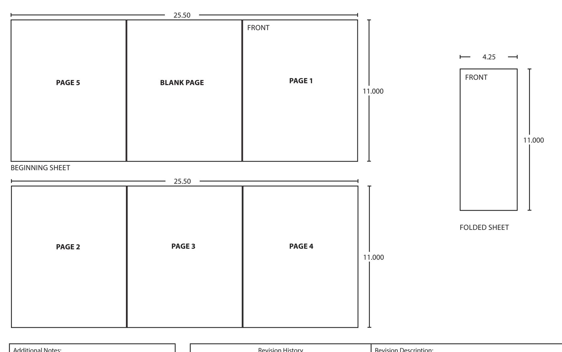
| Material | White | Paper | ||||
| Notes 1. printed two sides 2. printed black 3. tolerance ± .13 4. printed in country may vary 5. drawings not to scale | ||||||
| Revision History | Revision Description: | ||||||||||
|---|---|---|---|---|---|---|---|---|---|---|---|
| D | E | F | G | Н | J | D > Revised artwork | |||||
| 043228 | |||||||||||
| Material White Paper | Edited By | Approved By | EC Number | Release Date | |||||||
| D. Myers | M. Sasso | 043228 | 01-01-14 | ||||||||
| 1. printed two sides | Title 7949/ES7949 Series Blow-Open Control Box Instruction Sheet | ||||||||||
|
Creation Date
01-02-13 |
Number 19282 |
Revision
D |
||||||||
|
Created By
N/A |
Activity
3899 Hancock Expwy Security, CO 80911 |
||||||||||
| Software: InDesign CS6 | Allegion 2014 | ||||||||||