LCN 6030 Series Installation Instructions 106932
Open the original PDF document
View PDF

18503
6030 Series

Installation Instructions
4
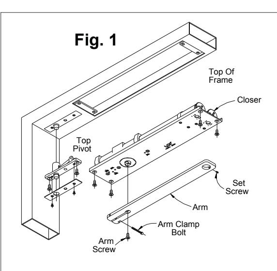
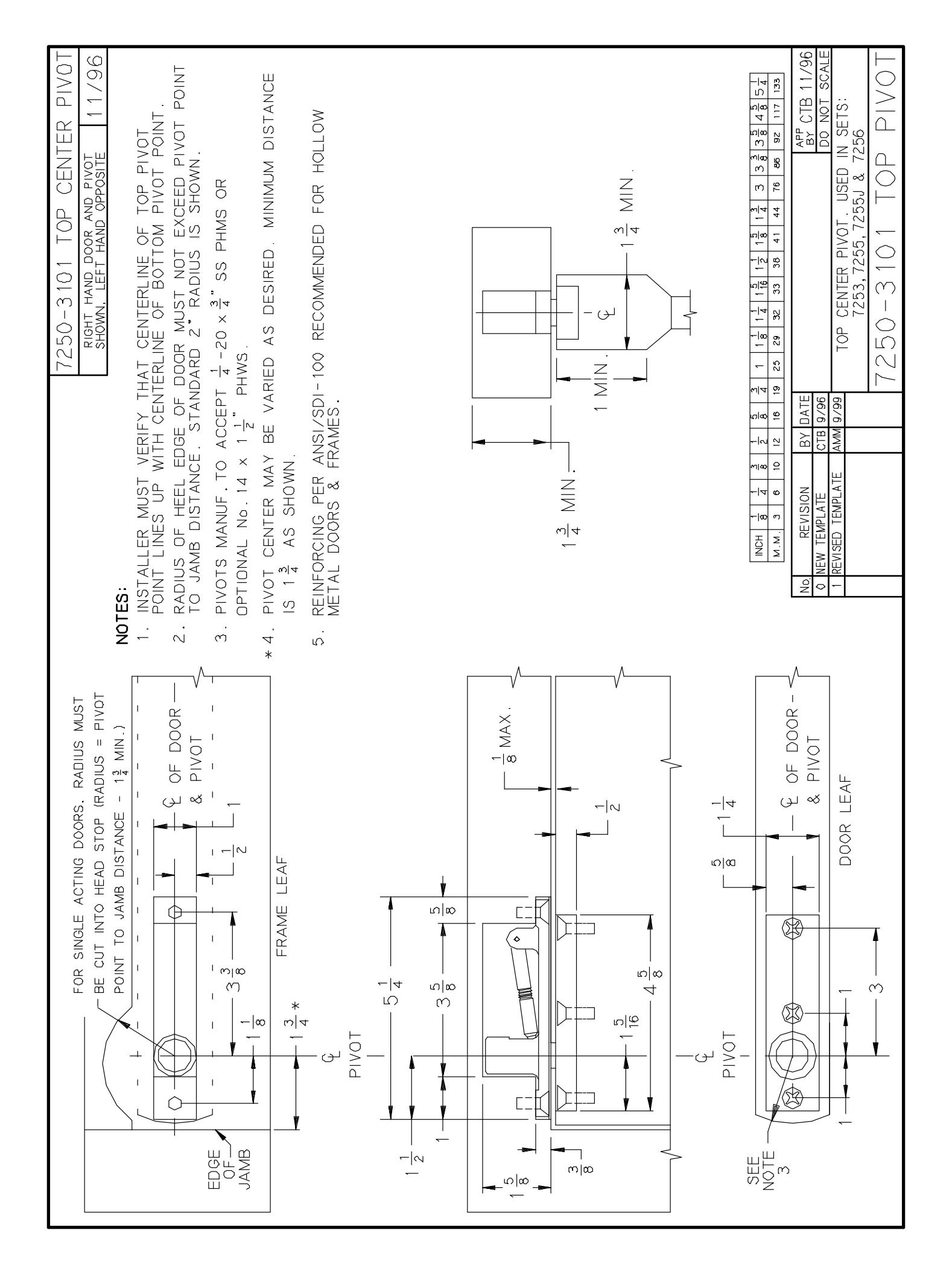
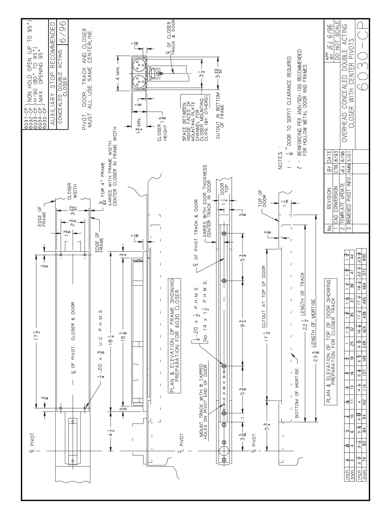
Prepare door and frame to recieve pivot and closer, per templates on pages 2 and 3. Install pivot and closer.
2
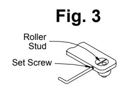
Bumper (and optional hold-open, when ordered) are factory installed. If a different degree of opening is required, follow step 2A. Insert roller first, then snubber in track as shown in FIG. 2. Install track in door mortise using screws provided. Tighten screws.
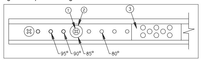
Slide bumper 3 away from post 2. Remove screw 1 and post 2, and reinstall in hole indicated above, tighten screw. Slide bumper 3 against post 2.
3
Door should now be hung on pivots. Refer to pivot installation sheet for details.
4
Attach arm to closer shaft with arm screw. Tighten screw securely.
A CAUTION A
Closer arm is under strong pressure to return. Hold it firmly during the next step.
5
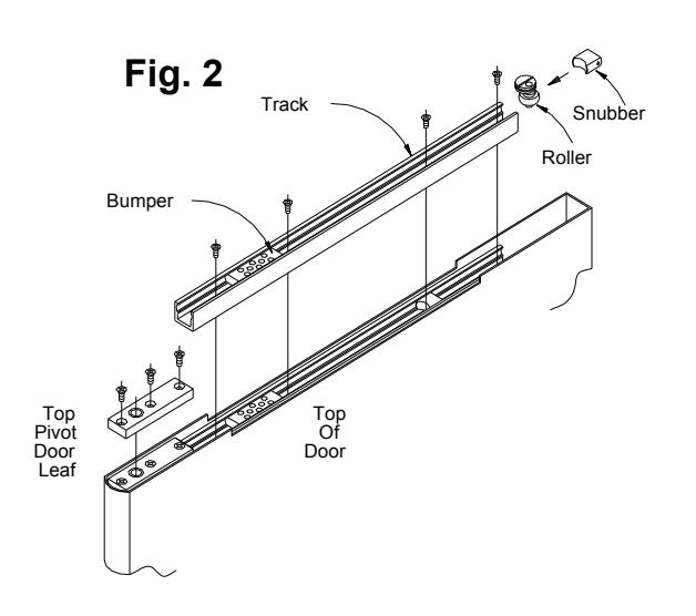
Open door to 45°. Pull arm toward door and slide roller stud under hole in arm. Install stud in arm with slot crosswise as shown in FIG. 3. Turn set screw in just enough to retain roller stud, but do not tighten firmly. Allow door to close, and with arm horizontal, tighten arm clamp bolt (at shaft end of arm) with hex key provided.
6
Closed door should be centered in frame. If not, open door part way and rotate roller stud about an eighth of a turn, using a screwdriver. (Set screw may need to be backed out slightly.) Repeat as needed till centered as required. When satisfied, tighten arm set screw securely. (When doors are paired, adjust both until edges match.) Open door, slide snubber into track at least 6" in from end. Allow door to close. This will automatically position the snubber correctly.
7
7a Location Adjustment of Hold Open Device
Slide bumper 3 away from pivot edge of door. Remove screw 1, post 2, adjusting cam 4, and screw 5. Slide holding clip 6 to locate screw holes over tapped holes in track as indicated below. Insert screw 5 and tighten securely. Replace cam 4, post 2, and screw1, tighten securely. Slide bumper 3 against post 2.
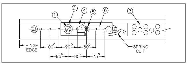
7b Intensity Adjustment of Hold Open Device
Test for release at hold open position. If holding force must be INCREASED, loosen screw 1 a quarter turn and slide cam 4 AWAY from pivot edge of door. Retighten screw 1 securely. For DECREASED holding force, cam 4 must be moved TOWARD pivot edge of door
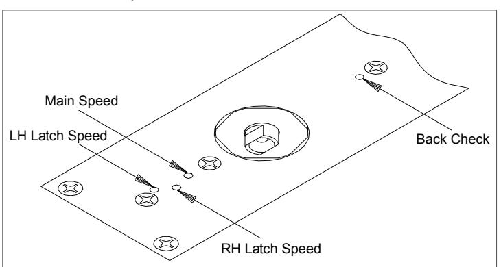
Regulation:
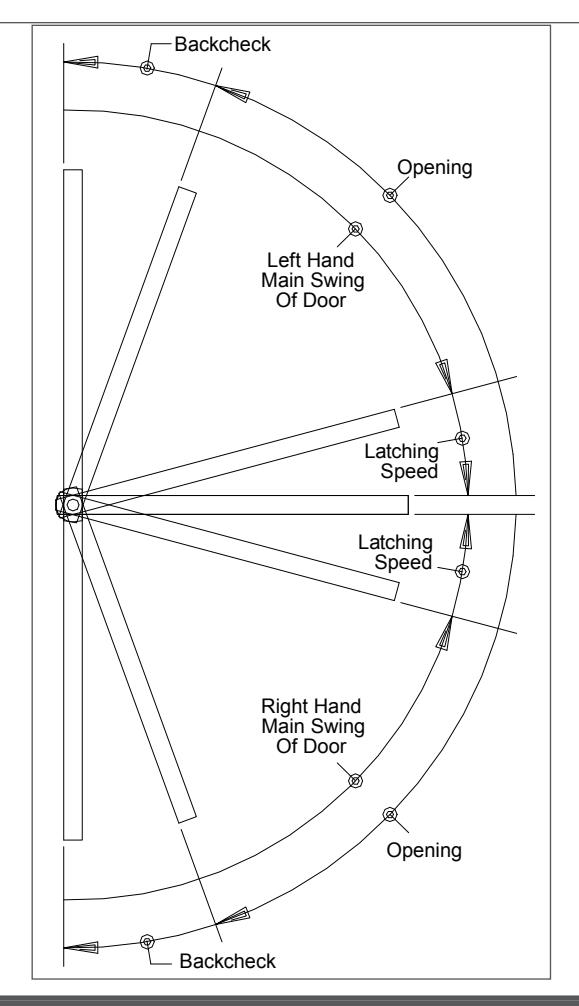
- 7c To regulate main swing speed: There is one main swing speed adjusting screw for both swings of door. If adjustment is required, turn screw clockwise to slow down main swing of door. To speed up main swing, turn screw counterclockwise. A normal closing time from 90° open position is 5 to 7 seconds, evenly divided between main swing speed and latch swing speed. Use a 32° hex wrench.
- 7d To regulate latch swing speed: There are two latch swing speed adjusting screws. Refer to diagram to identify hand of swing, and use screw marked LH (left hand) or RH (right hand). If adjustment is required, turn appropriate screw clockwise to slow down latch swing. To speed up latch swing, turn screw counterclockwise.
- 7e To adjust backcheck intensity: There is one backcheck adjustment screw for both swings of door. Adjust to lightest backcheck that will retard door opening speed during the last few degrees of opening. CAUTION: Do not set an abrupt backcheck or expect closer to act as a door stop. To increase backcheck, turn screw clockwise. To reduce backcheck, turn screw counterclockwise.
A CAUTION A
IMPROPER INSTALLATION OR REGULATION MAY RESULT IN PERSONAL INJURY OR PROPERTY DAMAGE. FOLLOW ALL INSTRUCTIONS CAREFULLY. FOR QUESTIONS, CALL LCN AT 877-671-7011
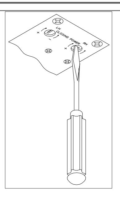
Closing Power Adjustment
Closer is shipped with minimum closing power, and power of each swing can be individually increased. To adjust, use spring adjustment screw that corresponds with hand of swing in regulation diagram. To increase, turn screw clockwise. Maximum adjustment is 36 turns.
| Table of Sizes | |||
|---|---|---|---|
| Maximum w | Catalog No. | ||
| Exterior | Interior | of Closer | |
| 38" (965 mm) |
6033
6034 |
||
| 36" (900 mm) | 48" (1220 mm) | ||
| 42" (1065 mm) | 54" (1370 mm) | 6035 | |
NOTE: Specify next higher closer where strong drafts exist.
| Customer Service | |||||
|---|---|---|---|---|---|
| 1-877-671-7011 | www.allegion.com/us | ||||

BEGINNING SHEET
| Additional Notes: |
|---|
| 1. None |
| Revision History | Revision Description: | |||||||||
|---|---|---|---|---|---|---|---|---|---|---|
| Н | J | К | L | М | N | H > Revised artwork | ||||
| 043228 | 1 | |||||||||
| Material | Edited By | Approved By | EC Number | Release Date | ||||||
| White Paper | D. Myers | M. Sasso | 043228 | 01-01-14 | ||||||
| Notes |
Notes
1. printed two sides 2. printed black |
Title | ||||||||
| 6030 Series Instruction Sheet | ||||||||||
| 3. tolerance ± .13 | Creation Date | Number | Revision | |||||||
|
4. printed in country may vary
5. drawings not to scale |
05-10-10 | 18503 | | H | |||||||
| 5. Grawings not to scale |
Created By
N/A |
Activity
3899 Hancock Expwy |
||||||||
| Software: InDesign CS6 | Security, CO 80911 © A | © Allegion 2014 | ||||||||