LCN 4410ME Installation Instructions 106925
Open the original PDF document
View PDF

4410ME Series

15022
Door closer with electronic release & Multi-point hold open
Installation Instructions
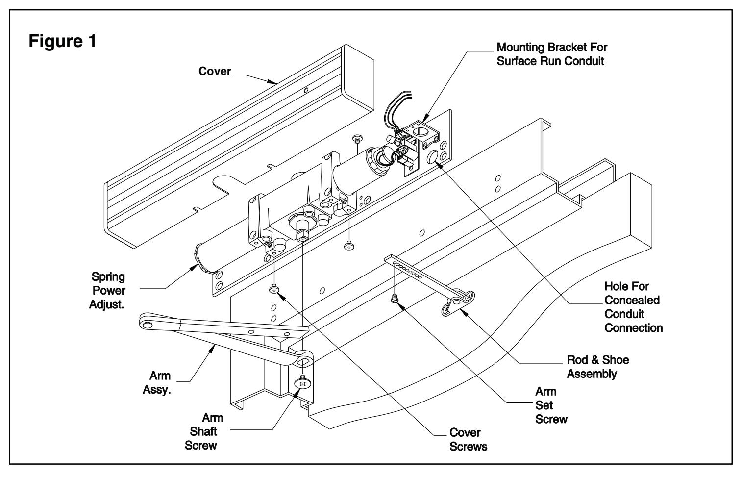
1 Closer Installation
1a Closer Information
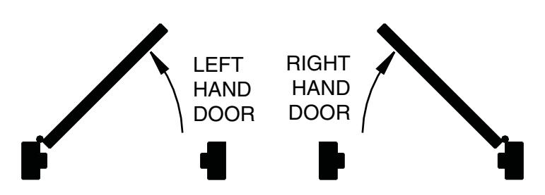
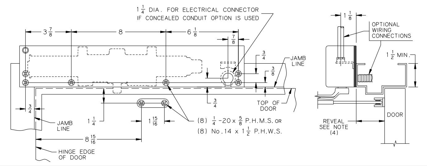
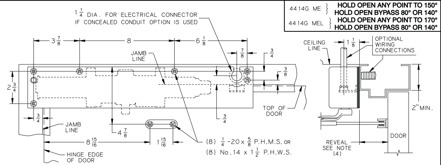
Closer is handed at the factory. The hand of the closer must match the hand of the door (see the door handing diagram below). Determine the closer mounting template to use - Standard or Flush-Ceiling (see page 4). Refer to the proper template for the entire installation
1b Voltage
Voltage supplied to the door frame MUST match voltage of the solenoid.
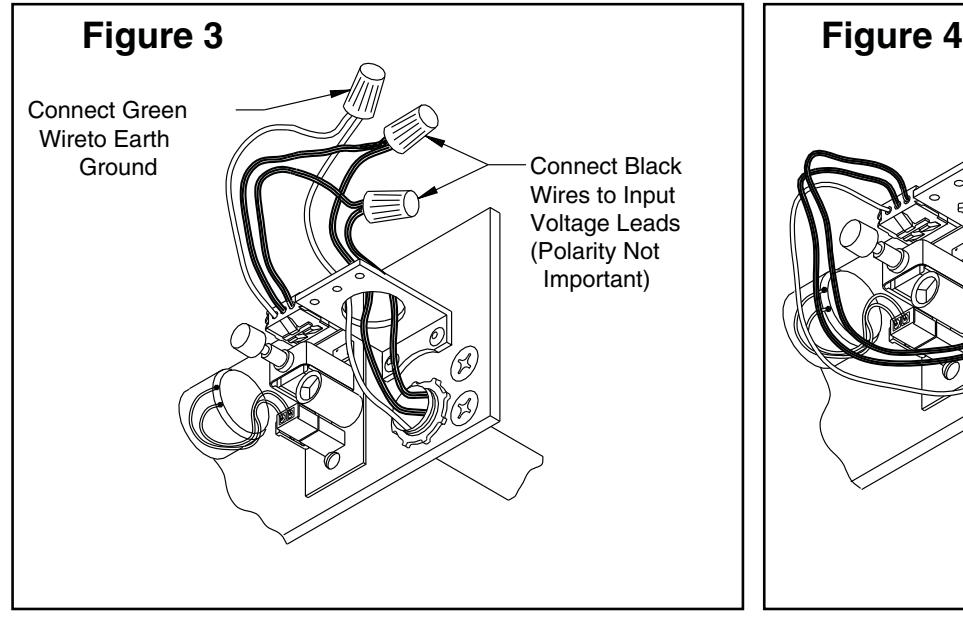
1c Before beginning this step, determine which type of wiring option will be used, and follow the corresponding instructions:
Concealed Wiring: see Figure 3 on page 3.
- a. Prepare the frame per the proper template on page 4. Be sure all the holes are dimensioned correctly before drilling and tapping.
- Assemble the conduit connector provided to the flexible conduit, then attach to the hole in the mounting plate.
- c. Secure the mounting plate to the frame with the screws provided.

HAZARDOUS VOLTAGE CAN SHOCK AND CAUSE SEVERE INJURY
Disconnect power before making any electrical connections or performing maintenance.
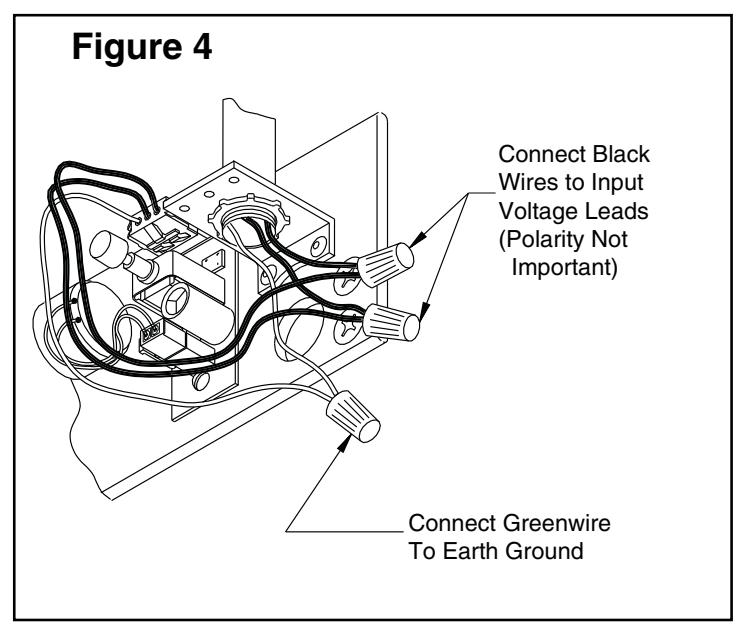
Surface Wiring: see Figure 4 on page 3.
- ① NOTE: Remove the knockout in the top of the cover.
- a. Prepare the frame per the proper template on page 4. Be sure all the holes are dimensioned correctly before drilling and tapping.
- b. Secure the mounting plate to the frame with the screws provided.
- c. Attach the surface run ½" EMT conduit to the hole in the bracket on the mounting plate. Be sure the conduit is securely attached to the bracket.
1d Wiring Connections
Make the wiring connections at this time. Connect the two black wires to the input voltage (polarity is not important). The green wire MUST be connected to an earth ground (see Figures 3 & 4 on page 3).
1e Main Arm
Place the main arm onto the shaft, approximately 90° to the closer body, and secure with the arm shaft screw.
1f Rod & Shoe
Attach the rod and shoe to the door, per the proper template on page 4, with the provided screws.
1g Insert the Rod
Open the door partway and insert the rod into the forearm, then close the door. Pull the Main Arm to a right angle (90°) to the door, insert the arm set screw, and tighten securely.
1h Regulate the Closer
Regulate the closer and perform the electrical checkout, as instructed on page 2, before installing the closer cover.
HOW TO TELL HAND OF DOOR:
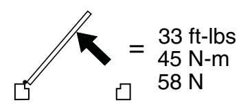
MAXIMUM OPENING FORCE
Customer Service
1-877-671-7011 www.allegion.com/us

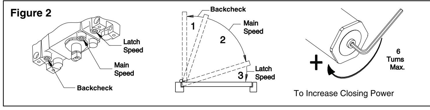
2 Regulation Instructions
See Figure 2 on the opposite page for regulating screw location, door control diagram & spring power adjustment
2a Spring Power Adjustment
DO NOT ALLOW THE DOOR TO SLAM INTO THE FRAME. The spring power should be adjusted only if more power is needed to close the door. Turning the spring adjustment B\cx" Allen Wrench clockwise will increase the spring power. Maximum adjustment is six (6) turns.
2b Regulation
A "normal" closing time from a 90° position is five (5) to seven (7) seconds, equally divided between the MAIN and LATCH SPEED . If adjustments are needed, use a C\cx" Allen Wrench. To adjust the MAIN SPEED , turn the regulating screw clockwise to slow the door speed, or counterclockwise to increase the door speed. LATCH SPEED is adjusted the same way. When adjusting the BACKCHECK, use the least amount of force necessary to sufficiently slow the swing of the door.To adjust the closer BACKCHECK , turn the regulating screw clockwise to increase the amount of force, or counterclockwise to reduce the amount of force. DO NOT USE THE ABRUPT BACKCHECK SETTING OR EXPECT THE CLOSER TO ACT AS A STOP!
Caution
Improper installation or regulation may result in personal injury or property damage. Follow all instructions carefully. For questions, call LCN at 877-671-7011
3 Electrical Checkout
After completion of installation & wiring, and with the unit properly powered, perform the following tests:
3a Hold Open the Door
With power on, open the door any position and release. The door should remain in the hold-open position within 10°. For a bypass model to hold open, the door must be opened beyond the degree of the door swing indicated on the label.
3b Door
If the door does not remain in the hold open position, push the on/ off switch. If the door still does not hold open, verify the proper voltage input at the solenoid leads.
3c Power Release
Turn the power off. The door should close completely.
3d Manual Release
To release manually, pull firmly on the door. The door should close completely.
3e Rechecking the System
The system should be checked at regular intervals. It is recommended that steps 3a-3c be repeated every 90 days.
4 Electrical Data for Door Holder Solenoid
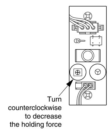
24V AC-DC Nominal +10% - 15% @ 0.075 Amp. Max. 120V AC-DC Nominal +10% - 15% @ 0.030 Amp. Max. 24 V Hold Open Force Adjustment
If the door is hard to pull out of the hold open position, adjust as shown.
Important
The closer leaves the factory set at a maximum holding force. The holding force may be decreased and increased again, but it cannot be increased beyond the original setting.
4410 ME
HOLD OPEN ANY POINT TO 150° HOLD OPEN BYPASS 80° OR 140° HOLD OPEN ANY POINT TO 170° HOLD OPEN BYPASS 80° OR 140°
LEFT HAND DOOR AND CLOSER SHOWN, RIGHT HAND OPPOSITE 5
"L" INDICATES LONG ARM

NOTES-
- 1. Voltage supplied to unit must match voltage shown on Sentronic label.
- 2. Locate closer and shoe from € of pivot when pivots are used. For use with swing clear hinges, consult factory.
- 3. Auxiliary stop is recommended. For use with overhead stops, shoe must be lowered to clear holder.
- 4. Long arm required for opening beyond 160°. Reveal not exceed 3 7/8" (5 3/4" FRAME).
- 5. Maximum stop thickness is 5/8".
- 6. Electric connector provided by LCN.
- 7. Reinforcing per ANSI\SDI 100 is recommended for hollow metal door and frames. | NCH | 1/4 | 3/8 | 1/2 | 5/8 | 3/4 | 7/8 | 1 1/8 | 1 1/4 | 1 1/2 | 1 1/16 | 2 |
| М.М. | 6 | 10 | 13 | 16 | 19 | 22 | 29 | 32 | 38 | 49 | 51 |
|---|---|---|---|---|---|---|---|---|---|---|---|
| INCH |
2
|
3 7/8 |
6
|
8 | 8 15 | 2 '4 " | 3.0. | 3'1" | 4.0. | ||
| М.М. | 65 | 70 | 98 | 146 | 156 | 203 | 227 | 700 | 900 | 925 | 1200 |

| Additional Notes: | ||||||
|---|---|---|---|---|---|---|
| 1. None | ||||||
| Revision History | Revision Description: | |||||||||
|---|---|---|---|---|---|---|---|---|---|---|
| G | Н | J | К | L | М | H > Revised artwork | ||||
| 038791 | 043228 | ] | ||||||||
| Material | Edited By | Approved By | EC Number | Release Date | ||||||
| White Paper | D. Myers | M. Sasso | 043228 | 01-01-14 | ||||||
| Notes | Title | |||||||||
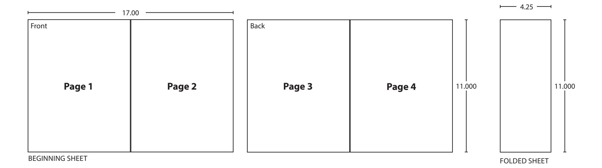
| 1. printed two sides | 4410ME Series Instruction Sheet | |||||||||
| 2. printed black 3. tolerance ± .13 | Creation Date | Number | Revision | |||||||
|
05-10-10 | 15022 | H | |||||||
| Created By N/A |
Activity
3899 Hancock Expwy |
• | ||||||||
| Software: InDesign CS6 | 1 Camuritus CO 00011 | © Allegion 2014 | ||||||||