LCN 4410HSA Series Installation Instructions 109706
Open the original PDF document
View PDF

4412 HSA

25074
Door Closer With Scanner Activated Hold Open
Installation Instructions
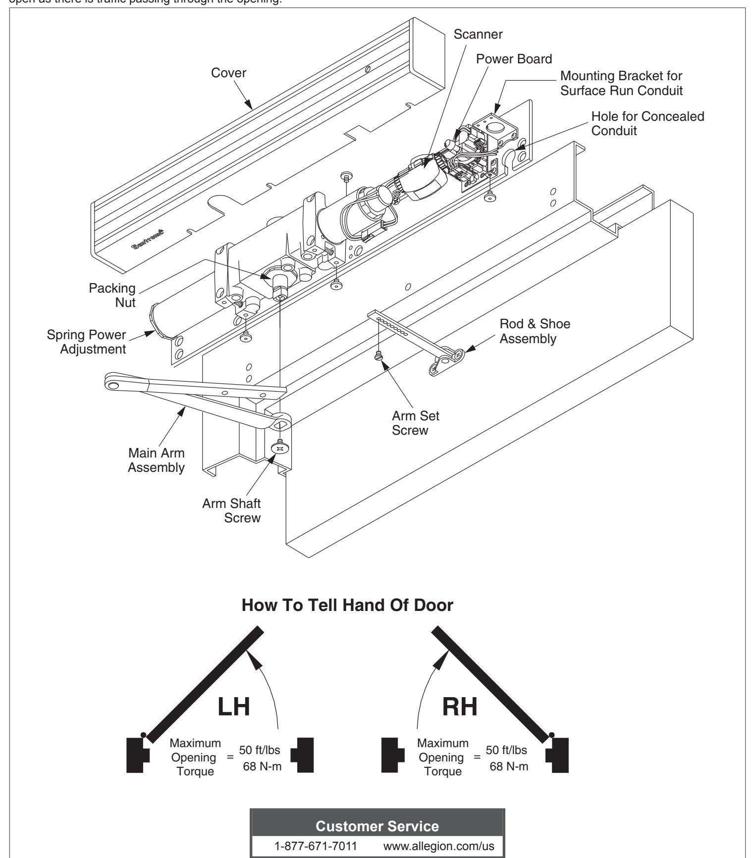
The LCN Sentronic HSA (Holder Scanner Activated) is a door closer with a scanner activated hold open feature designed to hold the door open as there is traffic passing through the opening.
Installation Instructions
Warning

HAZARDOUS VOLTAGE CAN SHOCK AND CAUSE SEVERE INJURY Disconnect power before making any electrical connections or performing maintenance.
1 Closer
The closer is handed at the factory, and marked with an "R" or "L" on top of the packing nut. The hand of the closer must match the handing of the door (see the door handing diagram on page 1).
2 Input Voltage
Input voltage supplied to the door frame must be 24V. Determine whether the wiring will be concealed or surface-run, and follow the remaining instructions carefully.
3 Wiring
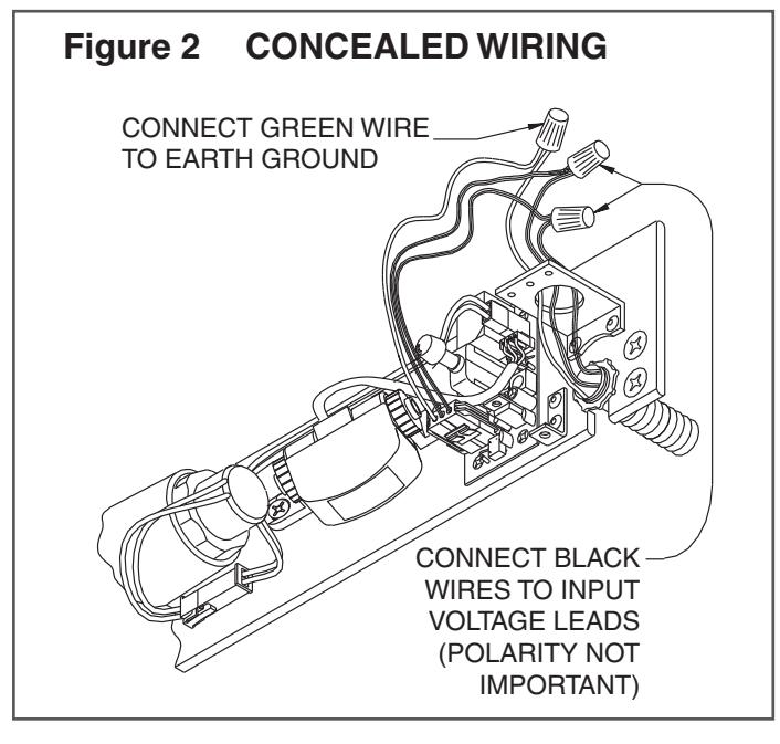
3a For concealed wiring:
See Figure 2 on page 3.
- 1. Prepare the frame with the proper template on page 6. Be sure all of the holes are dimensioned correctly before drilling and tapping.
- 2. Assemble the conduit connector provided to the flexible conduit, then attache to the hole in the mounting plate.
- 3. Secure the mounting plate to the frame with the screws provided.
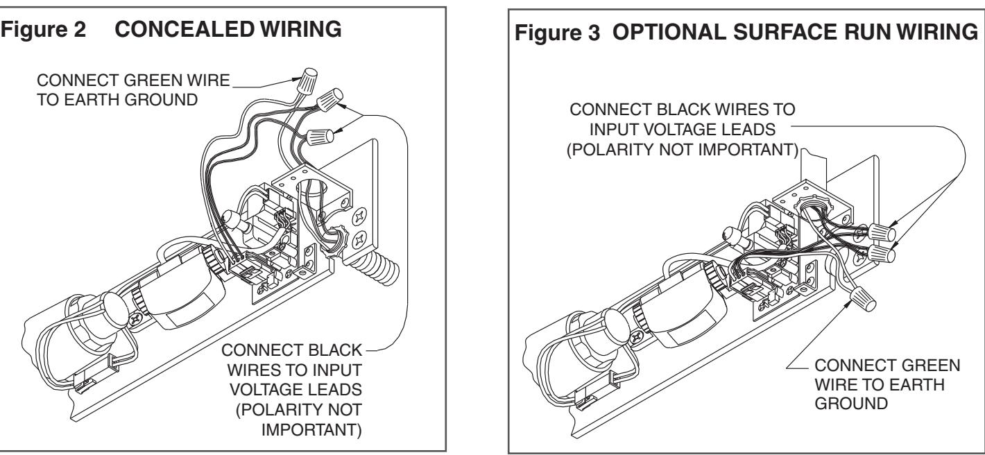
3b For surface wiring:
See Figure 3 on page 3.
- L NOTE: Remove the knockout in the top of the cover.
- 1. Prepare the frame with the proper template on page 6. Be sure all of the holes are dimensioned correctly before drilling and tapping.
- 2. Secure the mounting plate to the frame with the screws provided.
- 3. Attach the surface run Z\x" EMT conduit to the hole in the bracket on the mounting plate. Be sure the conduit is securely attached to the bracket.
4 Wiring Connections
Make your wiring connections at this time. Connect two black wires to the 24V input voltage. The green wire MUST be connected to an earth ground. See Figures 2 & 3 on page 3.
5 Arm Shaft
Place the main arm on the closer shaft, 90° to the closer body, and secure with the arm shaft screw.
6 Track Setup
Attach the rod & shoe to the door (per the template on page 5) with the screws provided.
7 Set Screw
Open the door partway, insert the rod into the forearm, then close the door. With the main arm at a right angle (90°) to the door, insert the arm set screw, and tighten securely.
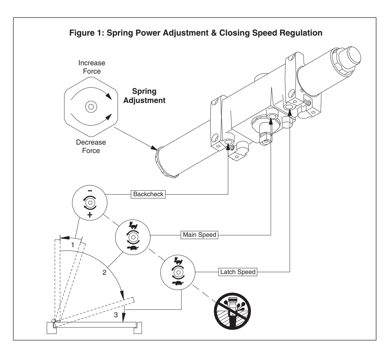
8 Spring Power Adjustment
See Figure 1 for the spring power adjustment diagram. To adjust the spring power, use a B\cx" allen wrench provided to turn the spring adjustment nut clockwise or counterclockwise the required number of turns to match the door width in the spring adjustment chart on page 6. DO NOT exceed 7 turns clockwise or 8 turns counterclockwise.
9 Closing Speed Regulation
The closing speed regulation is preset at the factory. Normally no adjustment is required. If adjustment is needed or desired, adjust the main speed and latch speed by turning the proper regulating screw for each (see Figure 1) clockwise to slow or counterclockwise to increase the speed. Do not allow the door to slam into the frame. A "normal" closing time from a 90° position is 5 to 7 seconds, equally divided between the main and latch speed. When adjusting the backcheck, use the least amount of force necessary to sufficiently slow the swing of the door. To adjust the backcheck, turn the regulating screw clockwise to increase the amount of force, or counterclockwise to reduce the amount of force. DO NOT USE AN ABRUPT BACKCHECK SETTING OR EXPECT THE CLOSER TO ACT AS A STOP!
10 Electrical Checkout
Perform the electrical checkout on page 4 before installing the closer cover.
Caution
Improper installation or regulation may result in personal injury or property damage! Follow all instructions carefully.
For questions, call LCN at 1-877-671-7011.
Electrical Checkout
① After completion of installation & wiring, and with the unit properly powered, perform the following steps:
1 LED
When 24V AC/DC power is applied, the LED on the scanner will flash on and off for 10 seconds, then turn off. The scanner LED will stay lit as long as any motion is detected. The scanner LED will remain lit for 15 seconds after motion has stopped, and then it turns off.
2 Scanner Sensitivity
Adjust the scanner sensitivity if required (Figure 4).
3 Door Hold Open Time
The door hold open time is controlled by the scanner, and it is set at 15 seconds. This time can be set at 30 seconds by setting switch 3 to "On" (see Figure 4).
4 Hold Open Operation
To check the hold open operation, open the door beyond 80°. The door should remain in the hold open position. The door should release and close 15 seconds after there is no motion at the door.
5 Continuous Hold Open
For continuous hold open, press the switch once to put the unit in the continuous hold open mode. Press the switch again to activate the timed hold open mode. The door must be opened beyond 80° for the hold open function to take effect.
Electrical Data
4412 HSA Scanner Activated Hold Open:
Voltage 24V AC/DC Nominal (+10% - 15%) Standby Current 0.010A
Hold Open Current 0.120A
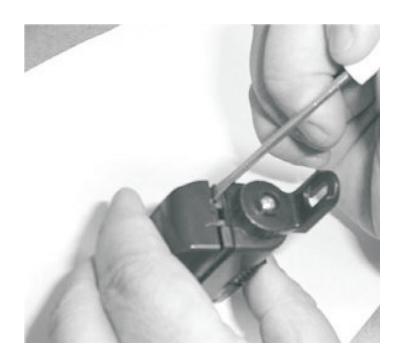
Figure 4: To Adjust Scanner Sensitivity
1. Insert a small screwdriver on the side of the housing and gently pry the cover off.
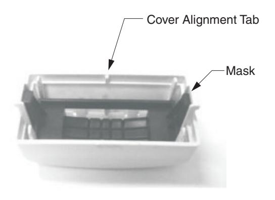
2. Keep mask and cover together as shown. Note: Cover alignment tab.
3. Set dip switch1 to ON to increase sensitivity.
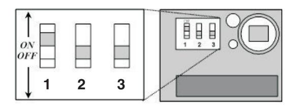
- Note: Leave switches 2 & 3 OFF.
- Snap mask and cover onto scanner housing. Note: Cover alignment tab fits into a notch on the bottom of the scanner housing.
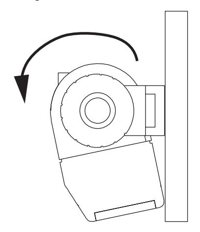
Figure 5
5. Rotate scanner towards mounting plate, as shown in Figure 5 (above).
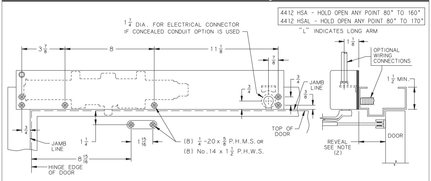
4412 HSA Standard Mounting
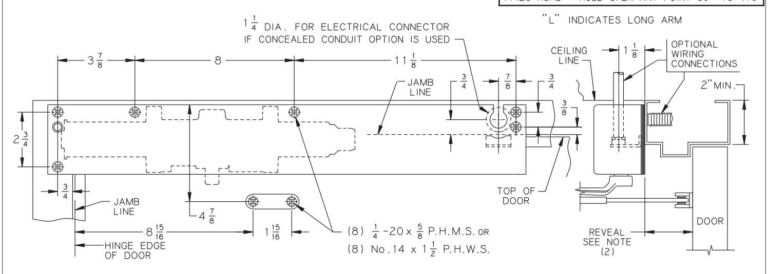
4412 HSA Flush Ceiling Mounting
Notes:
- 1. The voltage supplied to the unit must be 24 volts.
- 2. Long arms are required for opening beyond 160°; the reveal is not to exceed 3M\," (5C\v" frame).
- 3. Maximum stop thickness is B\,".
- 4. The electrical connector is provided by LCN.
- 5. If the door is hung on pivots, locate the closer and shoe from the centerline of pivot. if the door is hung on swing clear hinges, consult the factory.
- 6. Fllor or wall stops are recommended at maximum hold open.
- 7. For additional information on recommended use of this unit, consult the NFPA-72E pamphlet.
- 8. Reinforcing per ANSI/SDI-100 is recommended for hollow metal doors and frames.
| Inch | Z\v | C | Z\x | B | C\v | M | 1Z | 1Z\v | 1Z\x | 1ZB\zn | 2 | 2>\zn | 2C\v | 3M | 5C\v | 8 | 8ZB\zn | 11Z | 2' 4" | 3' 0" | 3' 1" | 4' 0" |
|---|---|---|---|---|---|---|---|---|---|---|---|---|---|---|---|---|---|---|---|---|---|---|
| M.M. | 6 | 10 | 13 | 16 | 19 | 22 | 29 | 32 | 38 | 49 | 51 | 65 | 70 | 98 | 146 | 203 | 227 | 283 | 700 | 900 | 925 | 1200 |