LCN 4311HSA Series Installation Instructions 111112
Open the original PDF document
View PDF

4311 HSA

25073
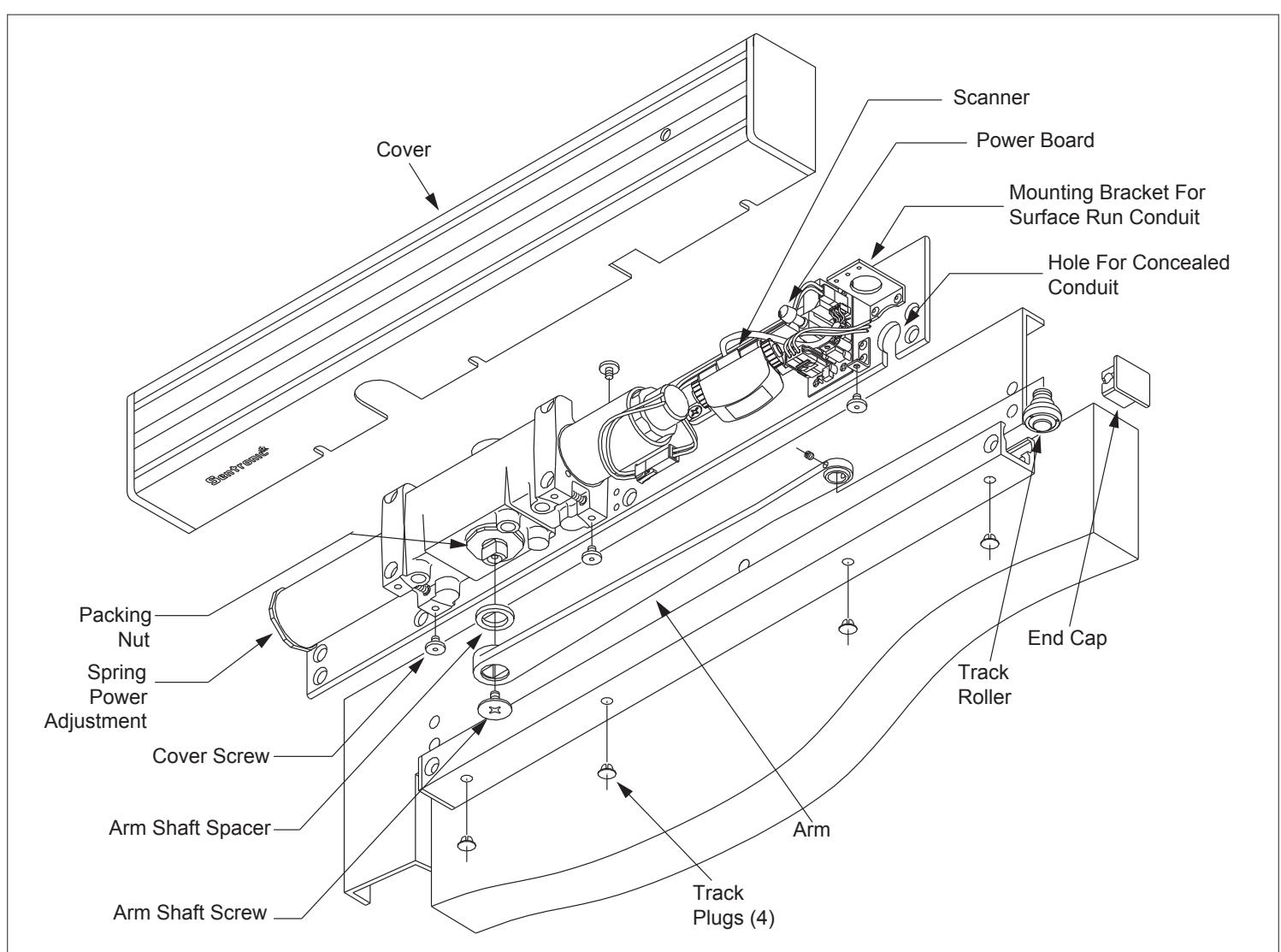
Door Closer With Scanner Activated Hold Open
Installation Instructions
The LCN Sentronic HSA (<u>H</u>older <u>S</u>canner <u>A</u>ctivated) is a door closer with a scanner activated hold open feature designed to hold the door open as long as there is traffic passing through the opening.
Warning

HAZARDOUS VOLTAGE CAN SHOCK AND CAUSE SEVERE INJURY Disconnect power before making any electrical connections or performing maintenance.
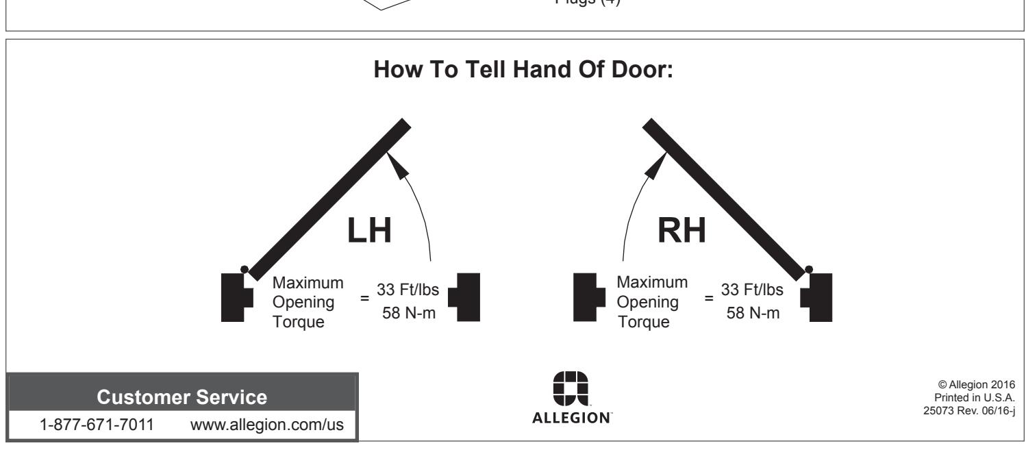
- 1a Closer is handed at factory and marked with an "R" or "L" on top of packing nut. The hand of closer must match hand of door (See door handing diagram on page 1).
- 1b Input voltage supplied to door frame must be 24V. Determine whether the wiring will be concealed or surface run, and follow the remaining instructions carefully.
-
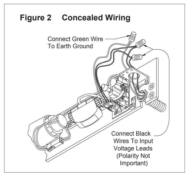
1c FOR CONCEALED WIRING: See
Figure 2
on page 3.
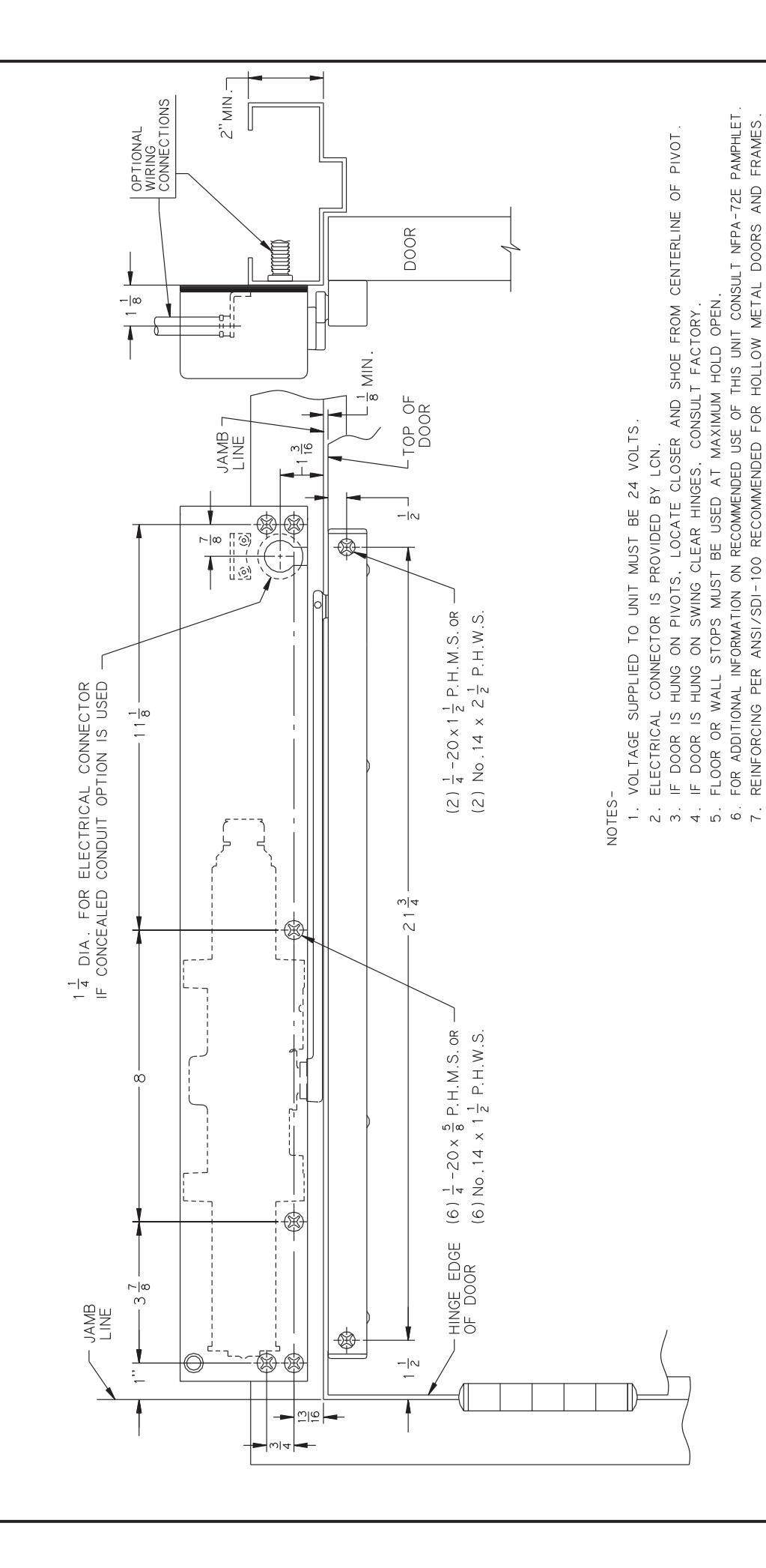
- a. Prepare frame per proper template on page 6. Be sure all the holes are dimensioned correctly before drilling and tapping.
- b. Assemble conduit connector provided to flexible conduit, then attach to hole in mounting plate.
- c. Secure mounting plate to frame with screws provided.
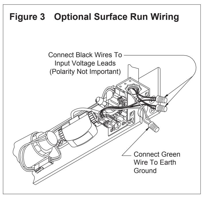
- 1d FOR SURFACE WIRING: See Figure 3 on page 3.
-
L
NOTE: Remove knockout in top of cover.
- a. Prepare frame per proper template on page 6. Be sure all holes are dimensioned correctly before drilling and tapping.
- b. Secure mounting plate to frame with screws provided.
- c. Attach the surface run 1/2" EMT conduit to hole in bracket on mounting plate. Be sure conduit is securely attached to bracket.
- 1e Make wiring connections at this time. Connect two black wires to 24V input voltage. Green wire MUST be connected to an earth ground. See Figure 2 or 3 on page 3.
- 1f Place arm shaft spacer on closer shaft, then place arm on closer shaft and secure with arm shaft screw.
- 1g Remove end cap from track and insert track roller. Reinsert end cap into end of track and insert track plugs. Using fasteners provided, mount track to door per template on page 6.
- 1h Loosen set screw in end of arm, open door approx. 30°, pull ar m over top of door and connect to track roller. Tighten set screw firmly.
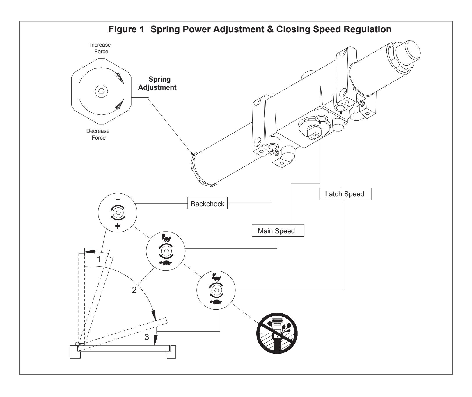
- 1i Spring Power Adjustment : See Figure 1 for spring power adjustment diagram. To adjust spring power, use a 5/32" allen wrench provided to turn spring adjustment nut clockwise or counter clockwise the required number of turns to match the door width in Spring Adjustment chart on page 6. DO NOT exceed 7 turns c.w. or 8 turns c.c.w. direction.
Caution
Improper installation or regulation may result in personal injury or property damage. Follow all instructions carefully. For questions, call LCN at 877 - 671 - 7011
- 1j Closing Speed Regulation is preset at factory. Normally no adjustment is required, if desired: adjust Main and Latch Speed by turning proper regulating screw (see Figure 1 ) clockwise to slow speed or c.c.w. to increase speed. Do not allow door to slam into frame. A "normal" closing time from a 90° position is 5 to 7 seconds, equally divided between Main and Latch Speed . When adjusting the Backcheck use the least amount of force necessary to sufficiently retard the swing of the door. To adjust Backcheck, turn regulating screw clockwise to increase amount of force or c.c.w. to reduce the amount of force. Do not use abrupt backcheck setting or expect closer to act as a stop!
- 1k Perform electrical checkout on page 4 before installing closer cover.
2 Electrical Checkout
- ① After completion of installation & wiring, and with the unit properly powered, perform the following steps:
- 2a When 24V AC-DC power is applied, LED on scanner will flash on and off for 10 seconds, then turn off. Scanner LED will stay lit as long as motion is detected. Scanner LED will remain lit for 15 seconds after motion has stopped and then turn off.
- 2b Adjust scanner sensitivity if required (figure 4).
- 2c Door hold open time is controlled by the scanner and is set at 15 seconds. This time can be set at 30 seconds by setting switch 3 to on (see figure 4).
- 2d To check hold open operation, open door beyond 80°. The door should remain in hold open. 15 seconds after there is no motion at the door, the door should release and close.
- 2e Continuous hold open Press switch once to put unit in continuous hold open mode. Press the switch again to activate the timed hold open mode. Door must be opened beyond 80° for hold open function to take effect.
3 Electrical Data
4311 HSA SCANNER ACTIVATED HOLD OPEN:
Voltage....................................
Standby Current 0.010A Hold Open Current 0.120A
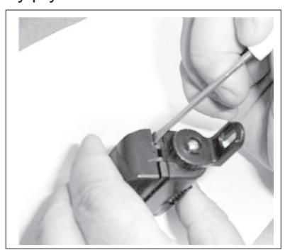
Figure 4:To Adjust Scanner Sensitivity
3a Insert a small screwdriver on the side of the housing and gently pry the cover off.
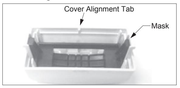
- 3b Keep mask and cover together as shown.
- ① Note: Cover alignment tab.
3c Set dip switch 1 to ON to increase sensitivty.
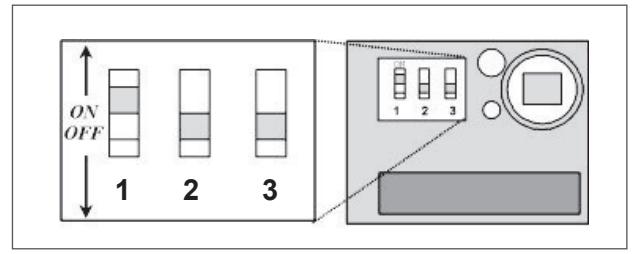
- i NOTE: Leave switches 2 & 3 OFF.
- 3d Snap mask and cover onto scanner housing.
- Note: Cover alignment tab fits into a notch on the bottom of the scanner housing.
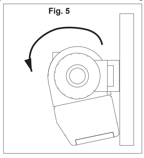
- 3e Rotate scanner towards mounting plate, as shown in Fig. 5.
4311 HSA - HOLD OPEN ANY POINT 80° TO 160° AUXILIARY STOP RECOMMENDED AT MAXIMUM HOLD OPEN
| Z | |
|---|---|
| Ī | J |
| _ | |
@
| INCH | - |∞ | -|4 | 1 | ଥାଦ | ω|4 | 13 | ~ |⊗ | - | -| ∞ | 1 16 |
-
| 4 |
1 = 2 |
|---|---|---|---|---|---|---|---|---|---|---|---|---|
| Σ. | 3 | 9 | 13 | 16 | 19 | 21 | 22 | 25 | 59 | 30 | 32 | 38 |
| INCH | 2 | 2 ½ | 80 | 11 1 8 | 213 | 2.4. | 0, 8 | . . | 4.0 | |||
| Σ. | 51 | 64 | 70 | 98 | 203 | 283 | 553 | 700 | 900 | 925 | 1200 |