LCN 4310ME Installation Instructions 106934
Open the original PDF document
View PDF

4310ME Series

18762
Door closer with electronic release & Multi-point hold open
Installation Instructions
1 Closer Installation
1a Closer Information
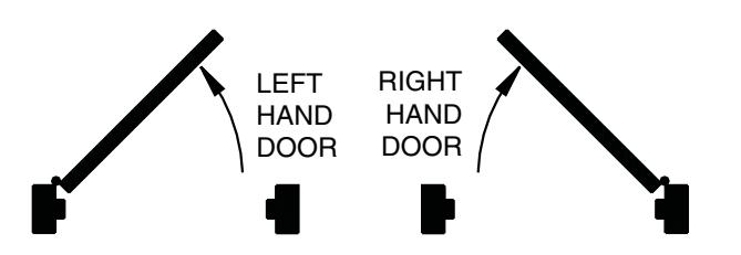
Closer is handed at the factory. The hand of the closer must match the hand of the door (see the door handing diagram below).
1b Voltage
Voltage supplied to the door frame MUST match voltage of the solenoid.
1c Before beginning this step, determine which type of wiring option will be used, and follow the corresponding instructions:
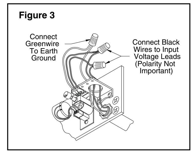
Concealed Wiring: see Figure 3 on page 3.
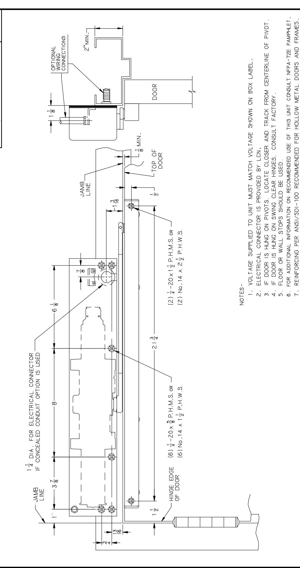
- a. Prepare the frame per the proper template on page 4. Be sure all the holes are dimensioned correctly before drilling and tapping.
- Assemble the conduit connector provided to the flexible conduit, then attach to the hole in the mounting plate.
- Secure the mounting plate to the frame with the screws provided.
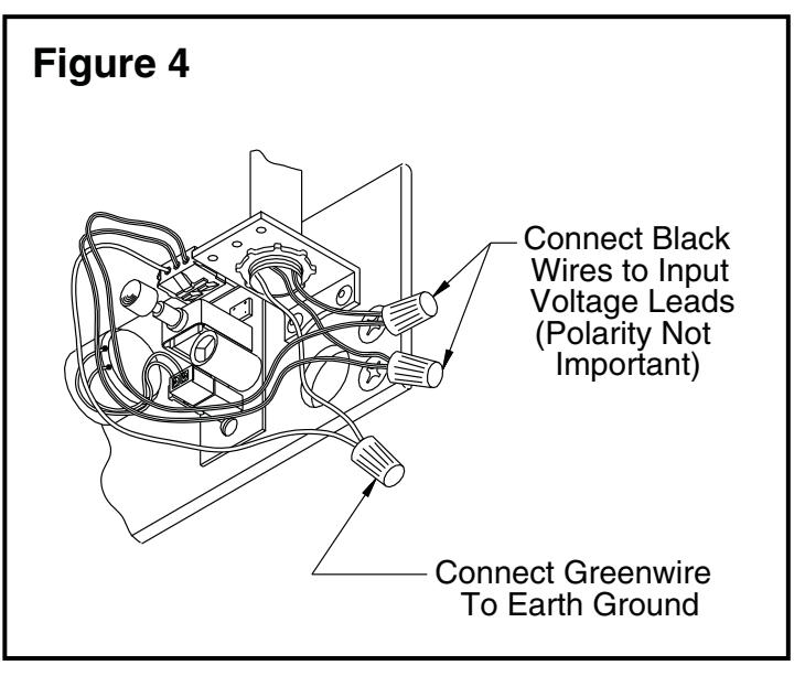
Surface Wiring: see Figure 4 on page 3.
⚠ WARNING ⚠

HAZARDOUS VOLTAGE CAN SHOCK AND CAUSE SEVERE INJURY
Disconnect power before making any electrical connections or performing maintenance.
(i) NOTE: Remove the knockout in the top of the cover.
- a. Prepare the frame per the proper template on page 4. Be sure all the holes are dimensioned correctly before drilling and tapping.
- Secure the mounting plate to the frame with the screws provided.
- c. Attach the surface run ½" EMT conduit to the hole in the bracket on the mounting plate. Be sure the conduit is securely attached to the bracket.
1d Wiring Connections
Make the wiring connections at this time. Connect the two black wires to the input voltage (polarity is not important). The green wire MUST be connected to an earth ground (see Figures 3 & 4 on page 3).
1e Spacer/Arm
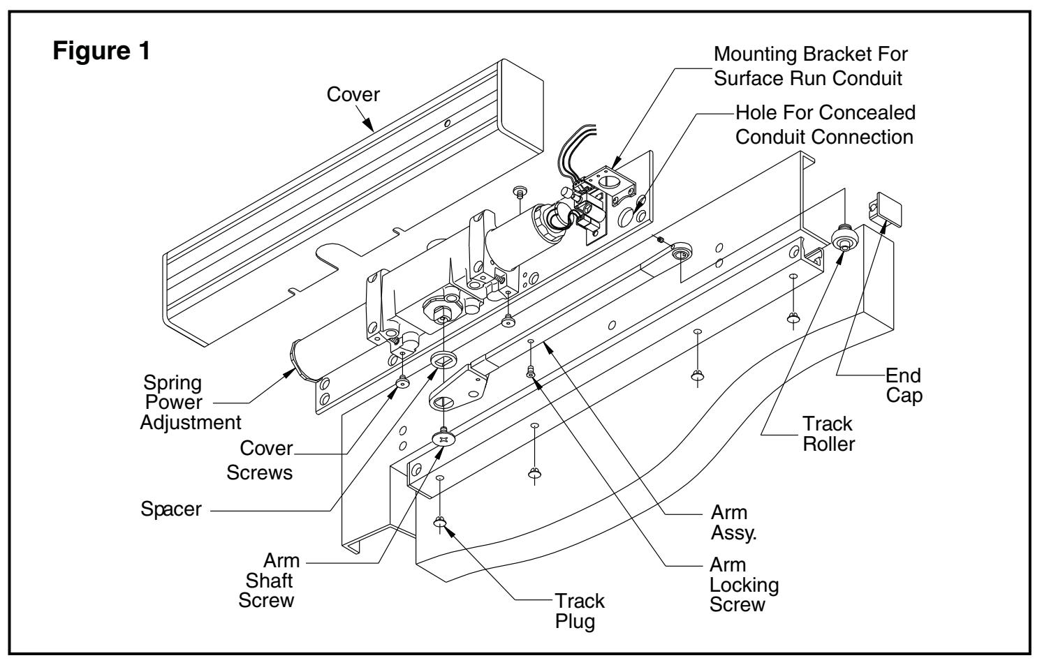
Place the spacer on the closer shaft, slide the arm onto the closer shaft, and secure it with the arm shaft screw (see Figure 1 on page 3).
1f Track Roller
Insert the track roller into the track, and end caps into both ends of the track. Place track plugs in the track where needed. Using the fasteners provided, mount the track on the door per the template on page 4.
1g Set Screw
Loosen the set screw in the end of the arm, open the door approximately 30°, pull the arm over the top of the door and connect to the track roller. Tighten the set screw firmly.
1h Electric Checkout
Regulate the closer and perform an electrical checkout, as instructed on page 2, before installing the closer cover.
1i Disengage the Swing Free Arm
To disengage the swing-free action of the arm, insert the locking screw (stored in the tube portion of the arm) into the shaft end of the arm, and tighten securely.
HOW TO TELL HAND OF DOOR:
Customer Service
1-877-671-7011 www.allegion.com/us

2 Regulation Instructions
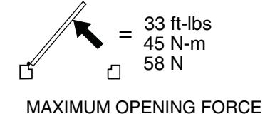
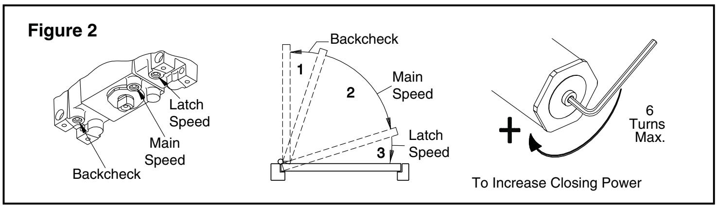
See Figure 2 on the opposite page for regulating screw location, door control diagram & spring power adjustment
2a Spring Power Adjustment
DO NOT ALLOW THE DOOR TO SLAM INTO THE FRAME. The spring power should be adjusted only if more power is needed to close the door. Turning the spring adjustment B\cx" Allen Wrench clockwise will increase the spring power. Maximum adjustment is six (6) turns.
2b Regulation
A "normal" closing time from a 90° position is five (5) to seven (7) seconds, equally divided between the MAIN and LATCH SPEED . If adjustments are needed, use C\cx" Allen Wrench. To adjust the MAIN SPEED , turn the regulating screw clockwise to slow the door speed, or counterclockwise to increase the door speed. LATCH SPEED is adjusted the same way. When adjusting the BACKCHECK , turn the regulating screw clockwise to increase the amount of force, or counterclockwise to reduce the amount of force. DO NOT USE THE ABRUPT BACKCHECK SETTING OR EXPECT THE CLOSER TO ACT AS A STOP!
Caution
Improper installation or regulation may result in personal injury or property damage. Follow all instructions carefully. For questions, call LCN at 877-671-7011
3 Electrical Checkout
After completion of installation & wiring, and with the unit properly powered, perform the following tests:
3a Hold Open
With power on, open the door any position and release. The door should remain in the hold-open position within 10°. For a bypass model to hold open, the door must be opened beyond the degree of the door swing indicated on the label.
3b Door
If the door does not remain in the hold open position, push the on/ off switch. Open the door again. If the shaft end of the arm still does not hold open, verify the proper voltage input at the solenoid leads.
3c Power Release
Turn the power off. The shaft end of the arm should rotate and pick up the rest of the arm, closing the door completely. Push the on/off switch again to restore the power.
3d Put on Closer Cover
After the electrical checkout is complete, fit the closer cover onto the closer and insert cover screws in proper locations. Hold the cover firmly against the mounting plate while tightening the cover screws securely.
3e Rechecking the System
The system should be checked at regular intervals. It is recommended that steps 3a-3c be repeated every 90 days.
4 Electrical Data for Door Holder Solenoid
24V AC-DC Nominal +10% - 15% @ 0.075 Amp. Max. 120V AC-DC Nominal +10% - 15% @ 0.030 Amp. Max. 24 V Hold Open Force Adjustment
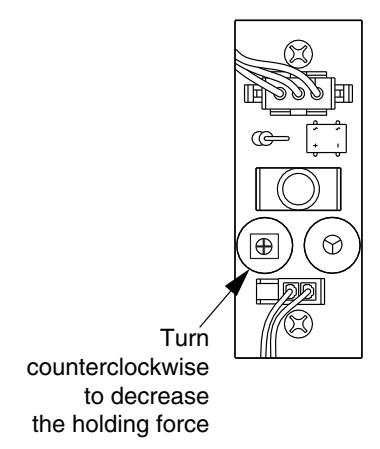
If the door is hard to pull out of the hold open position, adjust as shown.
Important
The closer leaves the factory set at a maximum holding force. The holding force may be decreased and increased again, but it cannot be increased beyond the original setting.
4314 ME HOLD OPEN ANY POINT TO 160° HOLD OPEN BYPASS 80° OR 140° AUXILIARY STOP RECOMMENDED RIGHT HAND DOOR AND CLOSER 12/96 SHOWN, LEFT HAND OPPOSITE 12/96
| NG | - |∞ | -|4 | -|2 | യ|വ | ω|4 | ~ |∞ | - |
_|∞
-|∞ |
|
|---|---|---|---|---|---|---|---|---|---|
| Α. | ю | 9 | 13 | 16 | 19 | 21 | 22 | 25 | 29 |
| NCH | 1 3 |
-
-|4 |
1 1/2 | 2 | 2 1/2 | 3 ~ | 6 1 | 8 | 213 |
| M.M. | θE | 32 | 38 | 51 | 64 | 98 | 156 | 203 | 553 |