LCN 4010 4020 4110 Series Fusible Link Installation Instructions 107134
Open the original PDF document
View PDF

4010, 4020, & 4110 Series

26367
Door Closers with Fusible Link Arms
Installation Instructions
The Fusible Link Arm is handed and cannot be reversed. Hand of arm and hand of door must correspond. The hand of arm is stamped on the vertical part of the shoe facing the Hold Open Nut. (CAN ONLY BE USED WITH SIZE 1-5 CLOSERS)
1 4010
- 1a For all degree's of door opening, increase the following dimension:
- Vertical distance from top jamb line to center of the shoe screw is increased from B\," to 1" .
- 1b For 90° to 100° opening, increase the following dimensions:
- (Reg & 4010-18 Drop Plate Mount) Distance from jamb edge to center of first screw on the shoe is increased from 12 B\zn" to 13 B\zn" .
- (Reg. Mount) Distance from door edge to center of the first screw on closer body is increased from 7" to 8"; (4010-18 Drop Plate Mount increase from 6 M\zn" to 7 M\zn".
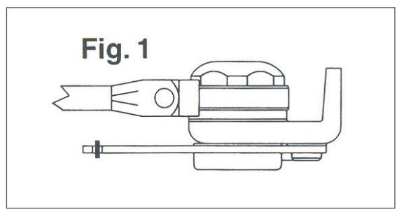
- Hold open nut must be on top. (see Fig. 1)
2 4020 (3 M\, Maximum Reveal)
- 2a Increase the vertical distance from the top door edge to the center of the shoe screw by the following dimensions:
- (No Drop Plate) Increased from B\," to 1" .
- (4020-18 Drop Plate) Increased from 1 C\v" to 2 Z\," .
- (4020-18G Drop Plate) Increased from 2 Z\x" to 2 M\," .
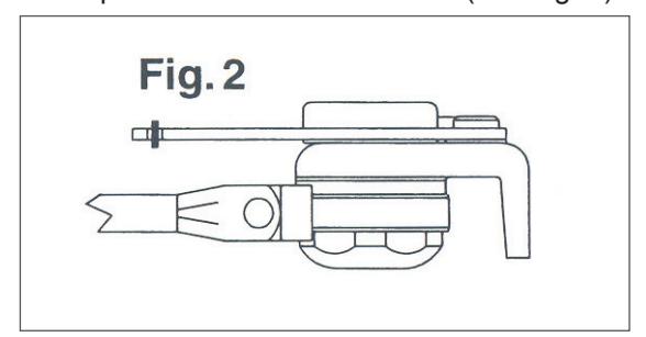
- 2b Hold Open nut must be on bottom. (see Fig. 2)
3 4110
- 3a (Reg. Mount) Vertical distance from stop face of frame to top screw on closer body is increased from 2 C\zn" to 2 C\v" .
- 3b (4110-18 Drop Plate Mount) Vertical distance from stop face of frame to top screw on drop plate is increased from C\v" to 1 B\zn" .
- 3c Hold open nut must be on top. (see Fig. 1)
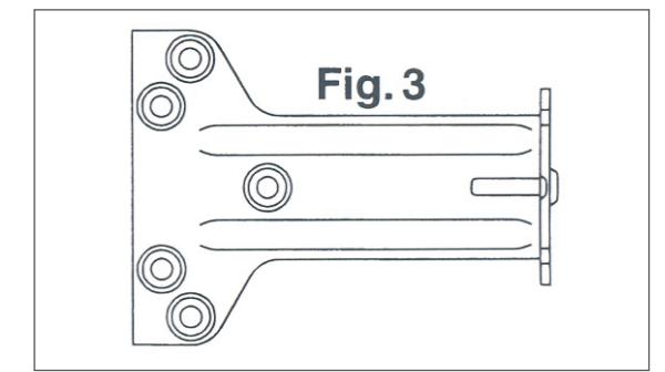
- 3d Requires installing the fusible link parallel arm soffit shoe (see Fig. 3) to standard shoe templating.
4 To Adjust Hold Open
- 4a Arm is pre-set to hold open at approximately 90°.
- 4b To change setting: Loosen adjusting nut; open door to 5° to 7° before the desired hold open position; firmly tighten adjusting nut.
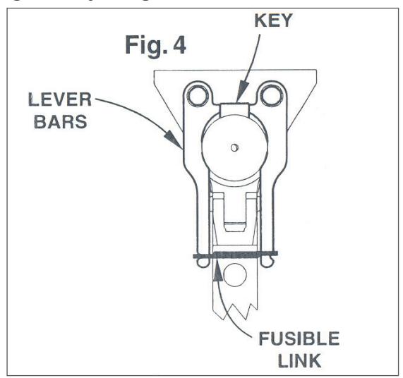
5 If Fusible Link Requires Replacement, Reassemble As Follows
- 5a Return door to original hold open position. This will automatically line up key & lever bars. (see Fig.4)
- 5b With pliers, carefully squeeze lever bars together just enough to install fusible link. DO NOT USE EXCESSIVE FORCE.
Customer Service 1-877-671-7011 www.allegion.com/us

© Allegion 2014 Printed in U.S.A. 26367 Rev. 01/14-c
| BEGINNING SHEET | FOLDED SHEET |
|---|---|
| Additional Notes: | |
|---|---|
| 1. None | |
| Revision History | · | Revision Description: | |||||||
|---|---|---|---|---|---|---|---|---|---|
| Α | В | С | D | E | F | C > Revised artwork | |||
| N/A | N/A | 043812 | İ | 1 | |||||
| Material White Paper | Edited By | Approved By | EC Number | Release Date | |||||
| D. Myers | M. Sasso | 043812 | 01-01-14 | ||||||
| 1. printed one side | Title 4010, 4020 & 4110 Series Fusible Link Instruction Sheet | ||||||||
|
Creation Date
04-27-10 |
Number 26367 |
Revision
C |
||||||
| 5. Grawii | 5. drawings not to scale |
Created By
N/A |
Activity
3899 Hancock Expwy |
||||||
| Software: InDesign CS6 | Security, CO 80911 | Allegion 2014 | |||||||